Cylindrical insert fluid injector / vacuum pump

a technology of injector and fluid, applied in the field of injector, can solve the problems of achieve the effect of less expensive production and different injector/vacuum pump performan

Inactive Publication Date: 2007-07-05
HARTLEY JOHN DOW
View PDF0 Cites 54 Cited by
  • Summary
  • Abstract
  • Description
  • Claims
  • Application Information

AI Technical Summary

Benefits of technology

[0019] The present invention relates to a method of producing hydrodynamic (or gas dynamic) fluid injectors, or vacuum pumps, in which a special cylindrical insert of appropriate material, geometry, and dimensions is fabricated and installed into either a common off-the-shelf or purpose built “tee” fitting, fixture, housing, or other suitable body to produce the complete injector / pump. In many, or perhaps even most, applications, the invention does not actually “work better” than conventional prior art hydrodynamic laminar flow venturi injectors and vacuum pumps, but in many instances, particularly in smaller quantities, it will prove much less expensive to produce. The invention offers a simplified approach to empirical design and testing of hydrodynamic (or gas dynamic) injectors intended for mass production by other more conventional methods, such as plastic injection molding. In addition, merely exchanging one insert for another with a different geometry produces different injector / vacuum pump performance.

Problems solved by technology

In addition, merely exchanging one insert for another with a different geometry produces different injector / vacuum pump performance.

Method used


Image

  • Cylindrical insert fluid injector / vacuum pump
  • Cylindrical insert fluid injector / vacuum pump
  • Cylindrical insert fluid injector / vacuum pump

Examples


Embodiment Construction

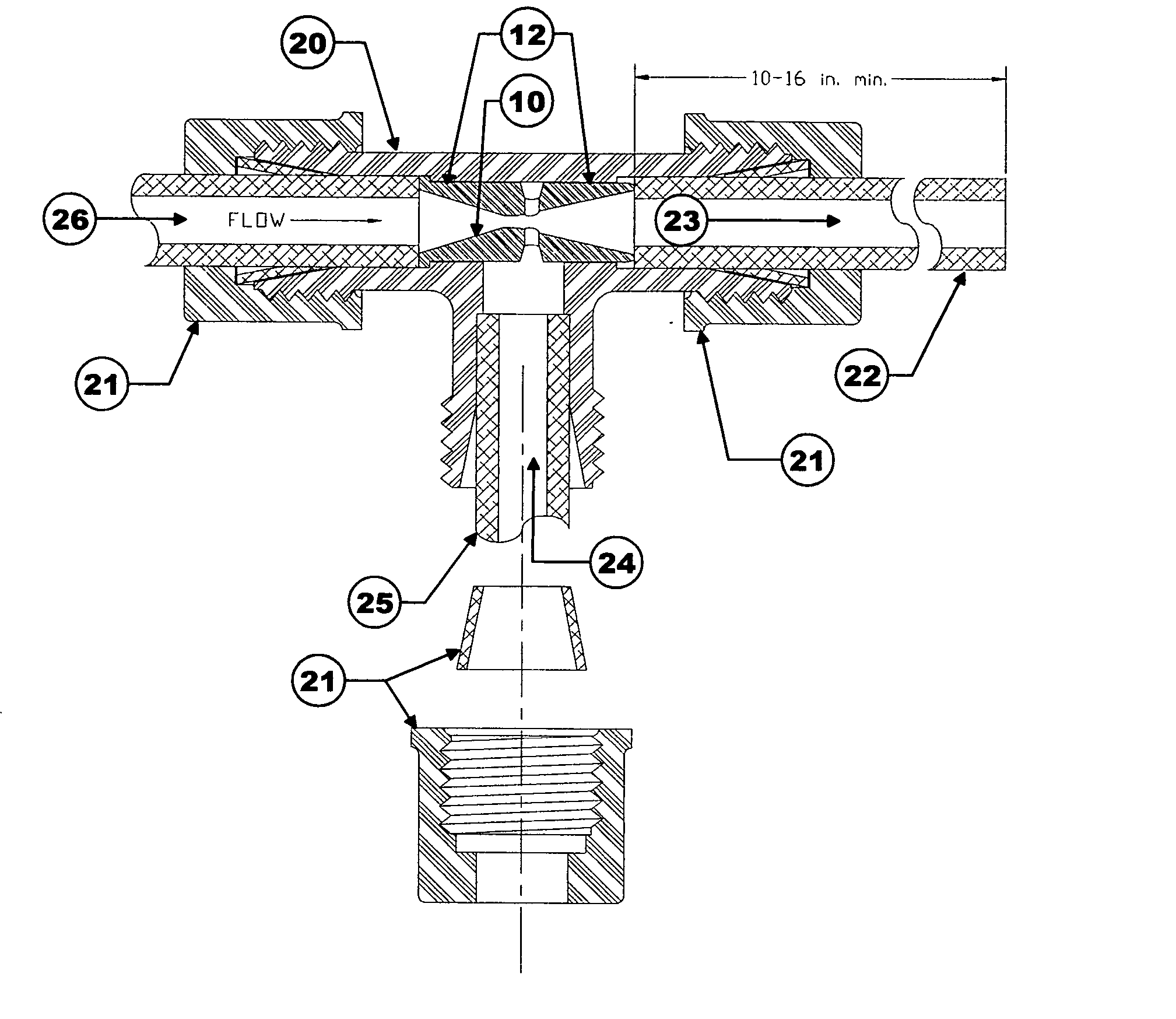
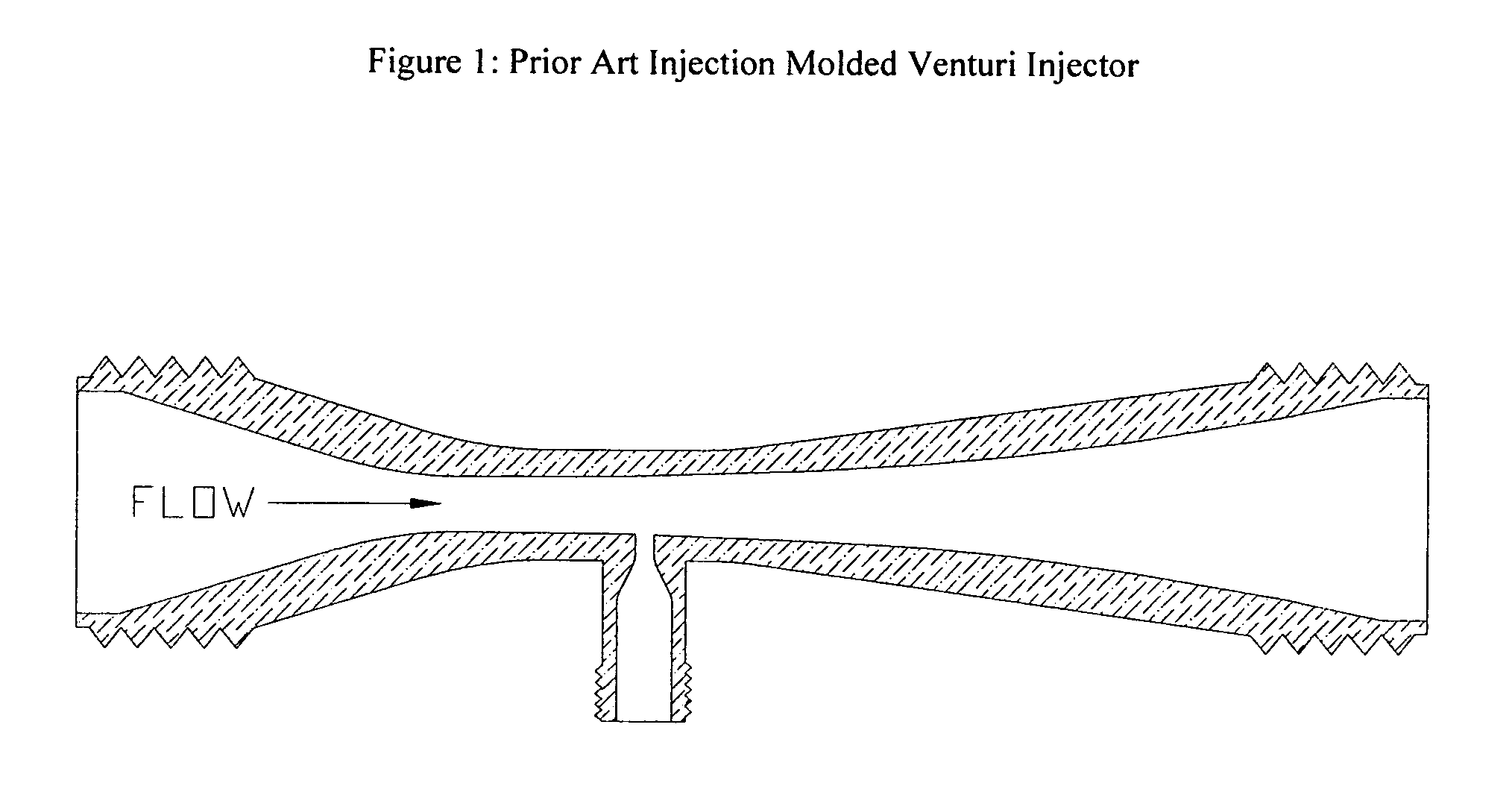
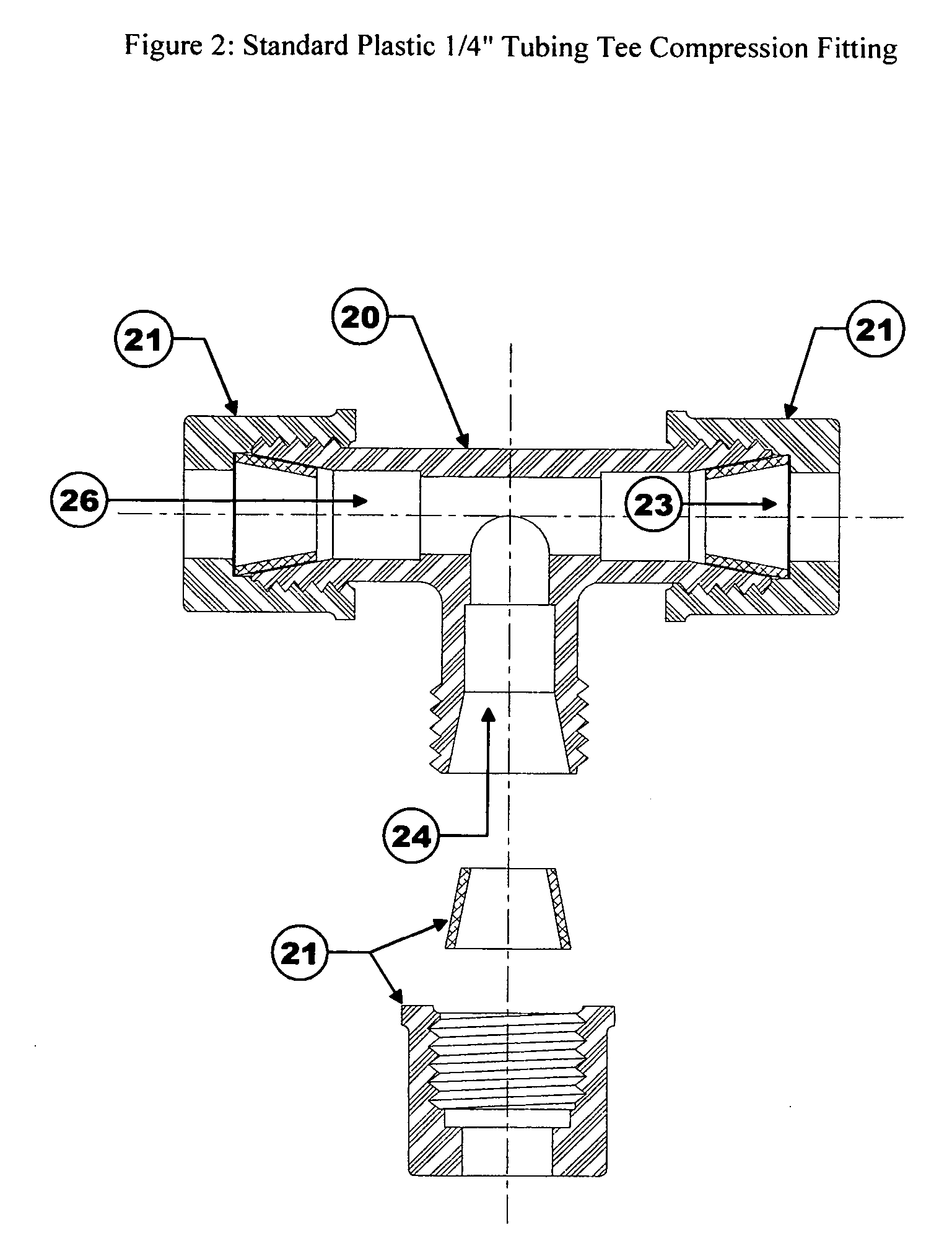
[0030] The present invention relates to a method of producing a hydrodynamic (or gas dynamic, hereinafter the term hydrodynamic should be taken to also include gaseous fluids as well as liquid fluids) fluid injector, cavitation fluid injector, or vacuum pump, in which a cylindrical tube of appropriate material, geometry, and dimensions (the insert) 10 (FIGS. 3, 4, 5, 6, 7, 8, 9) is installed into a common off-the-shelf or purpose built “tee” fitting, fixture, housing, or other suitable body (the body) 20 (FIGS. 2, 7, 8, 9). The assembled injector / vacuum pump (FIGS. 7, 8, 9) can then be connected to a manifold supplying inlet pressure and fluid flow needed to produce a predictable throat to injection (suction) passage pressure differential. Modular design of the cylindrical insert hydrodynamic injector / vacuum pump permits easy adaptation for specific fluid viscosity, flow rate, or other variables by replacing one insert 10 with another insert having different geometry and / or dimensio...


PUM

PropertyMeasurementUnit
pressureaaaaaaaaaa
pressureaaaaaaaaaa
inlet pressureaaaaaaaaaa

Abstract

A method of producing a hydrodynamic cavitation fluid injector, hydrodynamic vacuum pump, venturi fluid injector, or similar device in which a special cylindrical insert is combined with a suitable body, such as one of any number of common off-the-shelf or purpose built pipe and tube “tee” fittings. In its various embodiments, the insert has features, geometry, dimensions, and material characteristics suitable to the intended application, and is installed into the body through any of a variety of methods including threads, epoxy, press-fit, barbed press fit, plastic welding, solder, O-ring, bushing, flange, clamp, etc. to produce the complete injector/vacuum pump assembly. While the term hydrodynamic ordinarily applies only to liquid fluids, for the purposes of descriptions and claims of the present invention it should also be taken to include gaseous fluids. The injector/vacuum pump insert concept works just as well with gaseous fluids as with liquid fluids.

Description

FIELD OF THE INVENTION [0001] This invention pertains to pumping, injecting, and mixing, of fluids with devices similar to what are commonly known as venturi injectors. More specifically, the present invention relates to a method for producing an inexpensive fluid injector that creates a vacuum using a cylindrical insert that is installed into a standard or purpose built “tee” fitting, fixture, housing, or other suitable body. While the invention might sometimes take the geometric form of an ideal laminar flow venturi injector, in most embodiments the geometric form would more properly be identified as a turbulent flow cavitation injector. BACKGROUND OF THE INVENTION [0002] For over a century, millions of diverse fluid handling applications worldwide have commonly employed venturi injectors. The ordinary “carburetor” found on countless internal combustion engines is a complex form of venturi injector, where the pressure of air passing through a short venturi tube falls in proportion...

Claims


Application Information

Patent Timeline
Patent Type & Authority Applications(United States)
IPC IPC(8): B01F3/04F02M19/08
CPCB01F5/0413F02M19/08B01F5/0428B01F25/312B01F25/31242
Inventor HARTLEY, JOHN DOW
Owner HARTLEY JOHN DOW
Why Eureka
Try Eureka