Generating device

a technology of generating device and monitoring device, which is applied in the direction of generator/motor, instruments, transportation and packaging, etc., can solve the problems of increasing the cost of monitoring device of abnormal state of tire, inability to monitor inability to detect abnormal state of pneumatic pressure, etc., to achieve enhanced centrifugal force, low cost, and long time

Inactive Publication Date: 2007-07-05
USC
View PDF13 Cites 16 Cited by
  • Summary
  • Abstract
  • Description
  • Claims
  • Application Information

AI Technical Summary

Benefits of technology

[0008] According to the generating device of the present invention, since electricity can be supplied to the monitoring device of rotational state of tire and the like without using a battery or a loop coil antenna type power receiving device, it can be supplied to the monitoring device of rotational state at a lower cost for a long time.
[0009] Furthermore, the generating device of the present invention is constituted in such a manner that a pneumatically adjustable air passage is formed around an arm portion and/or a weight portion of the pendulum. Ac...

Problems solved by technology

Abnormal state of the pneumatic pressure of tire cannot, however, be monitored for a long time due to the short life of battery when the electricity of battery is used as an electric source for monitoring devices of abnormal state of tire.
Moreover, when the electricity received by the loop coil antenna type power receiving device is used as a source of the electricity for monitoring devices of abnormal state of tire, various sorts of constraints may be p...

Method used


Image

  • Generating device
  • Generating device
  • Generating device

Examples


first embodiment

[0031] Referring now to FIG. 4, a generating device of the first embodiment of the present invention will be described.

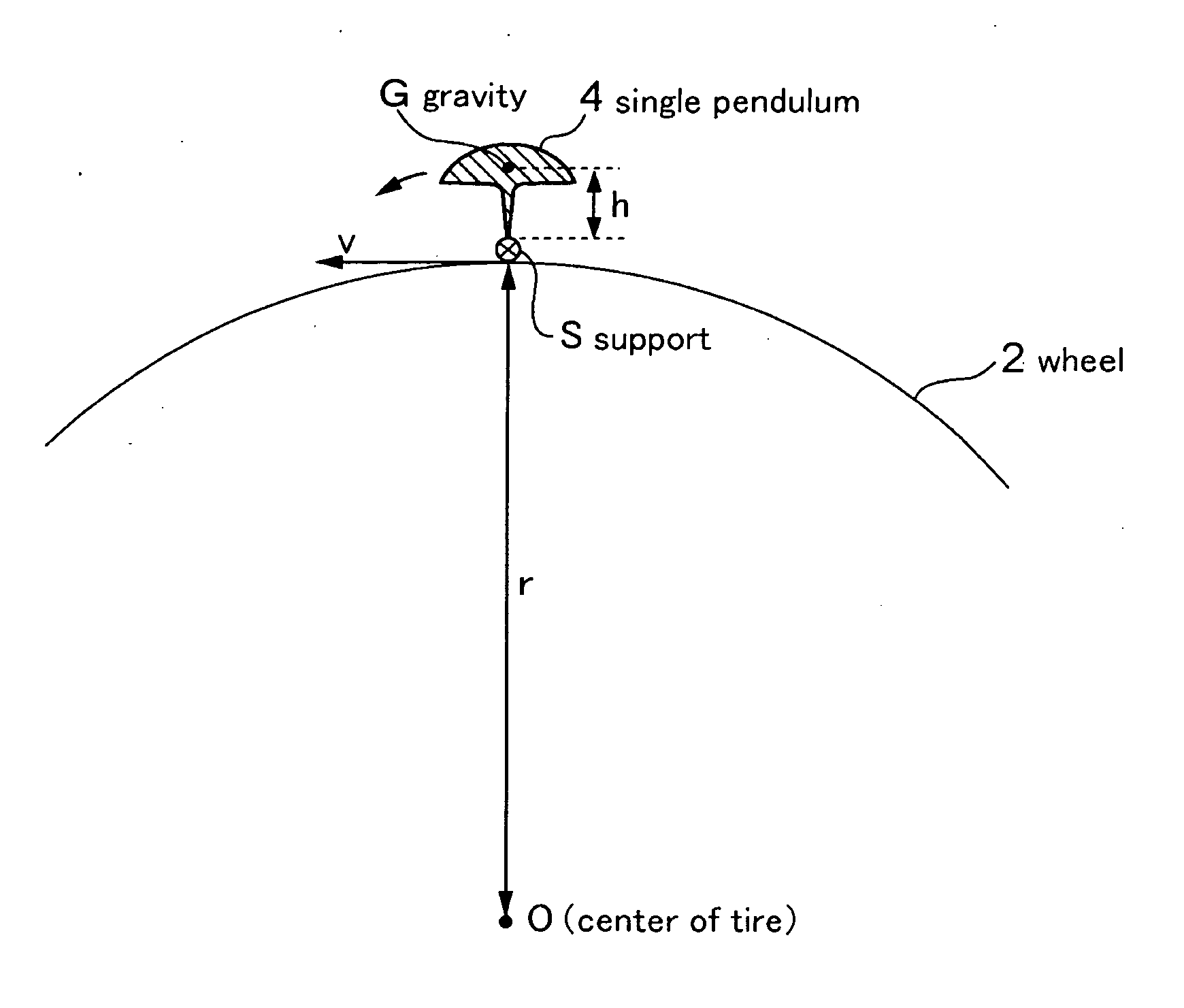
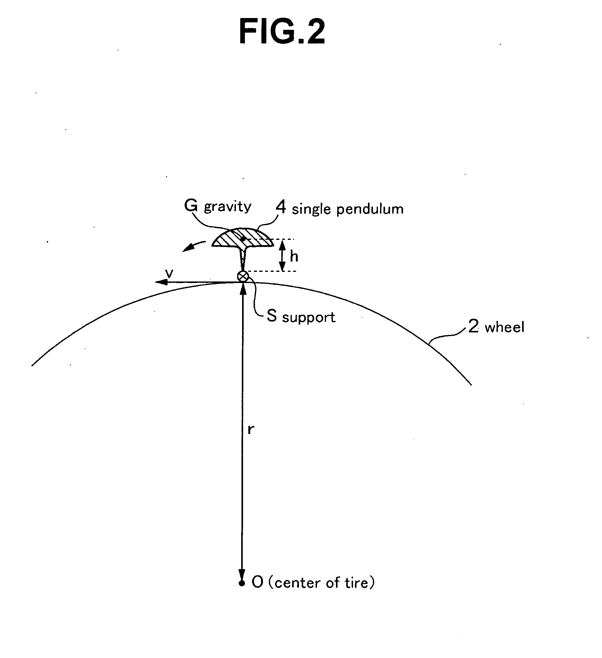
[0032] A generating device of the first embodiment of the present invention is placed in the interior of tire 1 and includes single. pendulum 4 supported at point S on the circumference of wheel 2, hammer 6 supported at point S′ on the circumference of wheel 2, spring 7 joining single pendulum 4 and hammer 6 by soft join, piezoceramics 8a and 8b converting the distortion generated by the vibration adding force from hammer 6 into a form of electricity, and cushion members 9a and 9b holding the positions of piezoceramics 8a and 8b. Single pendulum 4 has vibrational frequency as same as or of integral multiplication of the rotational frequency of tire 1. If the pendulum has vibrational frequency as same as or of integral multiplication of the rotational frequency of tire 1, single pendulum 4 may be replaced with other pendulums such as a balancing toy type pendulum.

[...

second embodiment

[0038] Referring now to FIG. 8, a generating device of the second embodiment of the present invention will be described about the structure.

[0039] A generating device of the second embodiment of the present invention is installed in the interior of tire 1, and as shown in FIG. 8, includes balancing toy type pendulum 5 supported at point S on the circumference of wheel 2 and magnets 12a and 12b are placed on the both end portions of support rod 11 which constitute balancing toy type pendulum 5. Further, balancing toy type pendulum 5 has vibrational frequency as same as or of integral multiplication of the rotational frequency of tire 1. Coils 13a and 13b are placed on the position diagonally to magnets 12a and 12b. In addition, in the present embodiment, magnets 12a and 12b are constituted of samarium-cobalt magnet of about three grams and designed to play a part as a weight. Moreover, if radius r of wheel 2 is about 200 mm, height h of support 10 is 4 mm and half-length l of suppor...


PUM


Abstract

A generating device to supply electricity to a monitoring device of abnormal state of tire at a lower cost for a long time. The generating device includes a single pendulum 4, a hammer 6 supported at a point S′ on the circumference of a wheel 2, a spring 7 joining the single pendulum 4 and the hammer 6 by soft join, piezoceramics 8a and 8b converting distortion generated by the vibration adding force from the hammer 6 into a form of electricity, and cushion members 9a and 9b holding the positions of the piezoceramics 8a and 8b. A single pendulum 2 has vibrational frequency as same as or of integral multiplication of the rotational frequency of a tire 1.

Description

BACKGROUND OF THE INVENTION Field of the Invention [0001] The present invention relates to a generating device for supplying electricity to a monitoring device of rotational state which monitors abnormal pneumatic pressure of a body of rotation such as a tire. [0002] A monitoring device of abnormal rotation of tire as a body of rotation will be described as an example of the present invention. Since long, a monitoring device of abnormal state of tire has been known that includes a pressure sensor detecting the internal pressure of tire, a temperature sensor detecting the internal temperature of tire and a radio transmitter wirelessly sending the information detected by the pressure sensor and the temperature sensor to a receiver attached to a vehicle body, monitors the abnormal state of the pneumatic pressure of tire, and advises drivers about the abnormal state of the pneumatic pressure of tire when the abnormal state of pneumatic pressure occurred. [0003] In this type of monitorin...

Claims


Application Information

Patent Timeline
IPC IPC(8): H02N3/00H02N11/00B60C23/02G08B23/00
CPCB60C23/041H02N2/183H02N2/18B60C23/0411
Inventor SAKAI, YASUHIROTOBE, JUNICHITSUDA, EISUKEKATO, TAMOTSU
Owner USC
Why Eureka
Try Eureka