Discharge cell for ozonizer

a discharge cell and ozonizer technology, applied in the field of plate-type discharge cells, can solve the problems of reducing the discharge current in the discharge gap, deteriorating the ozone generating efficiency, and increasing the manufacturing cost of the discharge cell, so as to improve the ozone generating efficiency, and reduce the thickness of the high-voltage insulating plate

Inactive Publication Date: 2007-07-05
SUMITOMO PRECISION PROD CO LTD
View PDF1 Cites 21 Cited by
  • Summary
  • Abstract
  • Description
  • Claims
  • Application Information

AI Technical Summary

Benefits of technology

[0016] An object of the present invention is to provide a high-performance and economic discharge cell for ozonizer, capable of reducing an insulating plate cost, while preventing an ozone generating efficiency from deteriorating.
[0017] Another object of the present invention is to provide the discharge cell for ozonizer, capable of increasing the ozone concentration without depending on a reduction of a gap amount in a discharge gap, and of more efficiently increasing the ozone concentration, when the gap amount is smaller.

Problems solved by technology

As a result, it has become clear that a thickness of an insulating plate, especially a thickness of a high-voltage insulating plate, which has contributed to increase a manufacturing cost of the discharge cell, is not essential in terms of the ozone generating efficiency, as this has been conventionally considered.
That is to say, the high-voltage insulating plate is intended to electrically insulate the inner high-voltage electrode from the outer (back surface side) refrigerant (cooling water), and if the sufficient thickness is not ensured, the reactive current flows to the refrigerant (cooling water) side and the discharge current in the discharge gap decreases, thereby deteriorating the ozone generating efficiency.

Method used


Image

  • Discharge cell for ozonizer
  • Discharge cell for ozonizer
  • Discharge cell for ozonizer

Examples


first embodiment

[0072] Next, the effect of the thickness of the high-voltage insulating plate in the discharge cell of the present invention on the ozone concentration is quantitatively indicated to clarify the effect of the present invention.

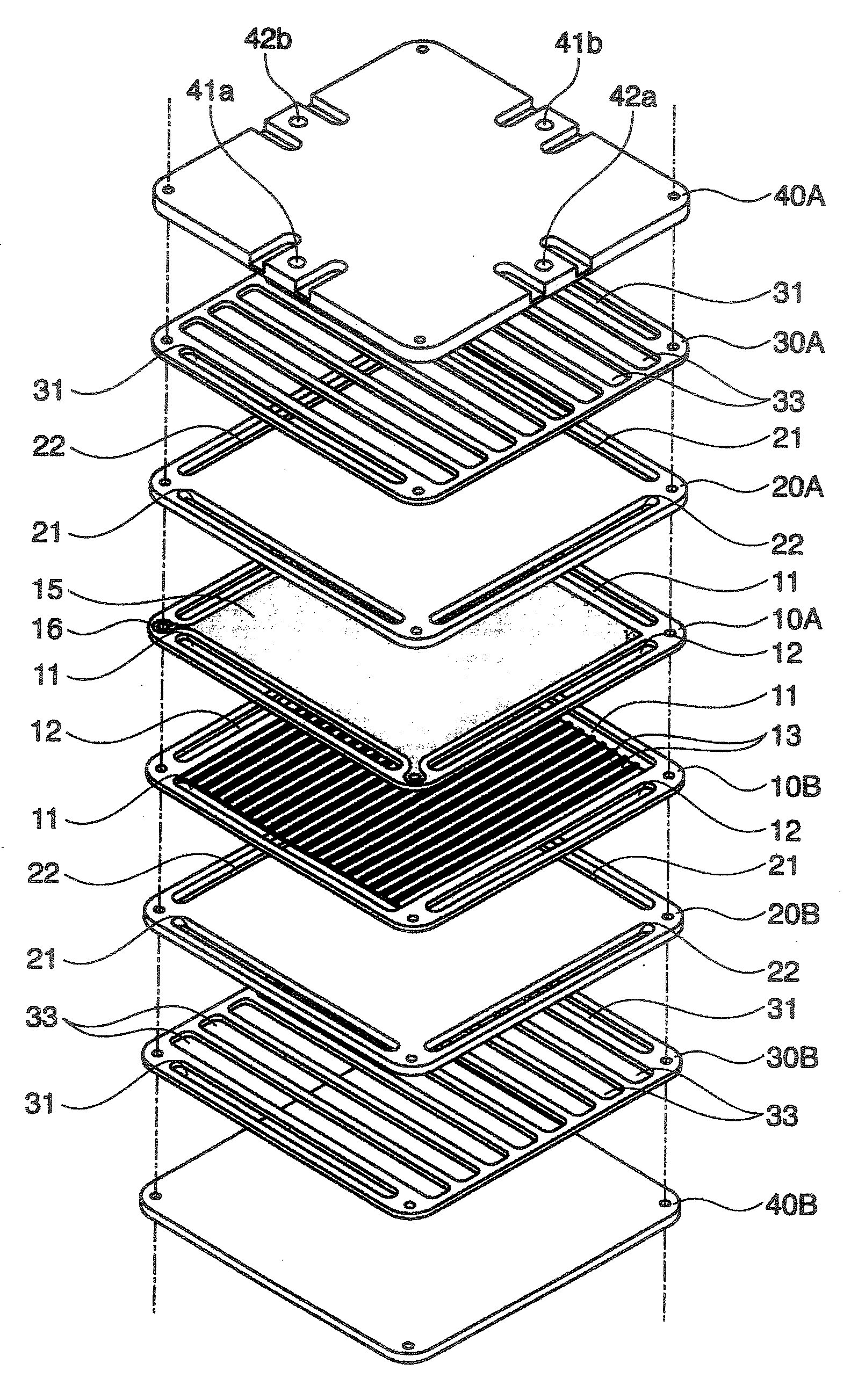
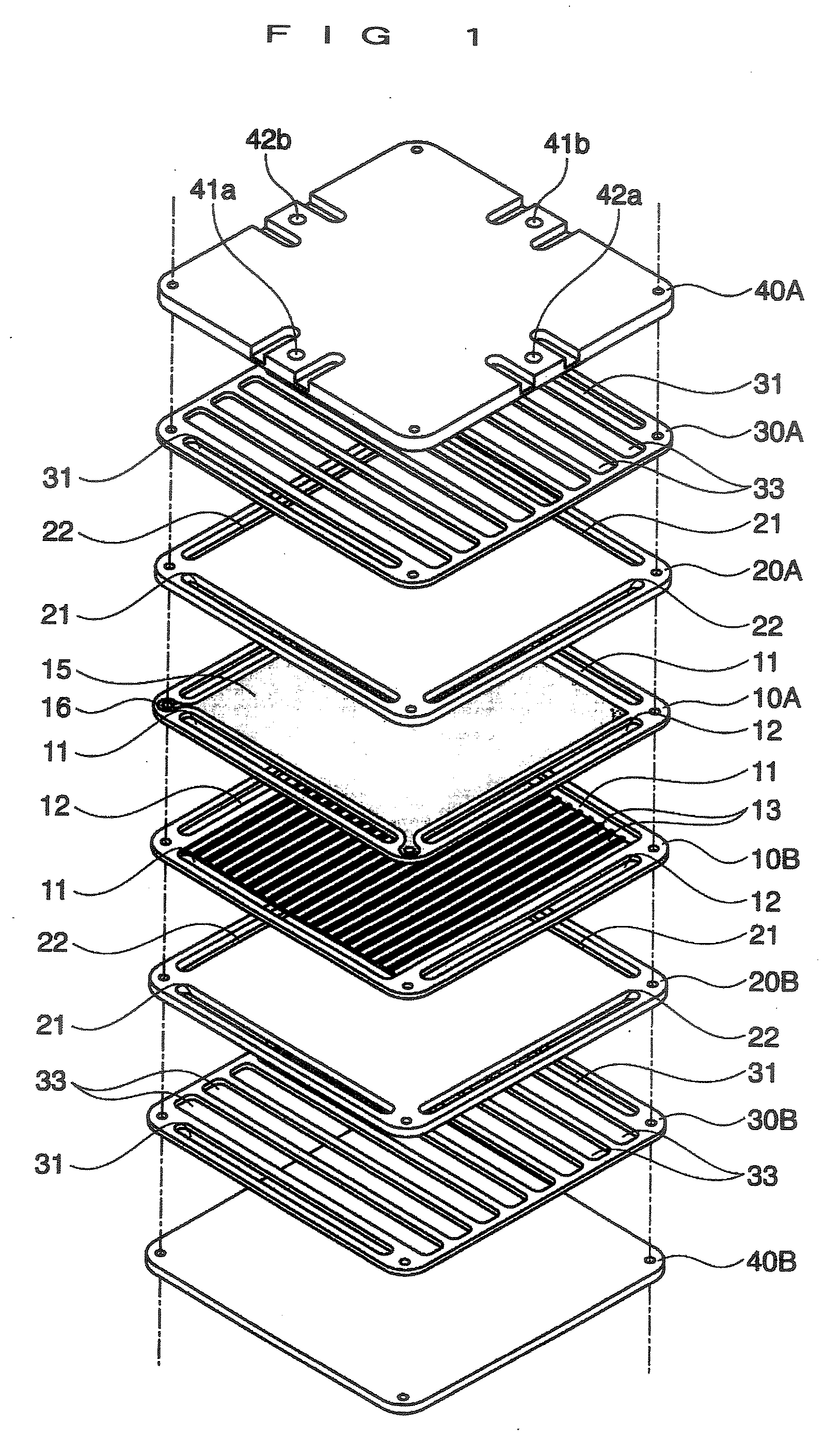
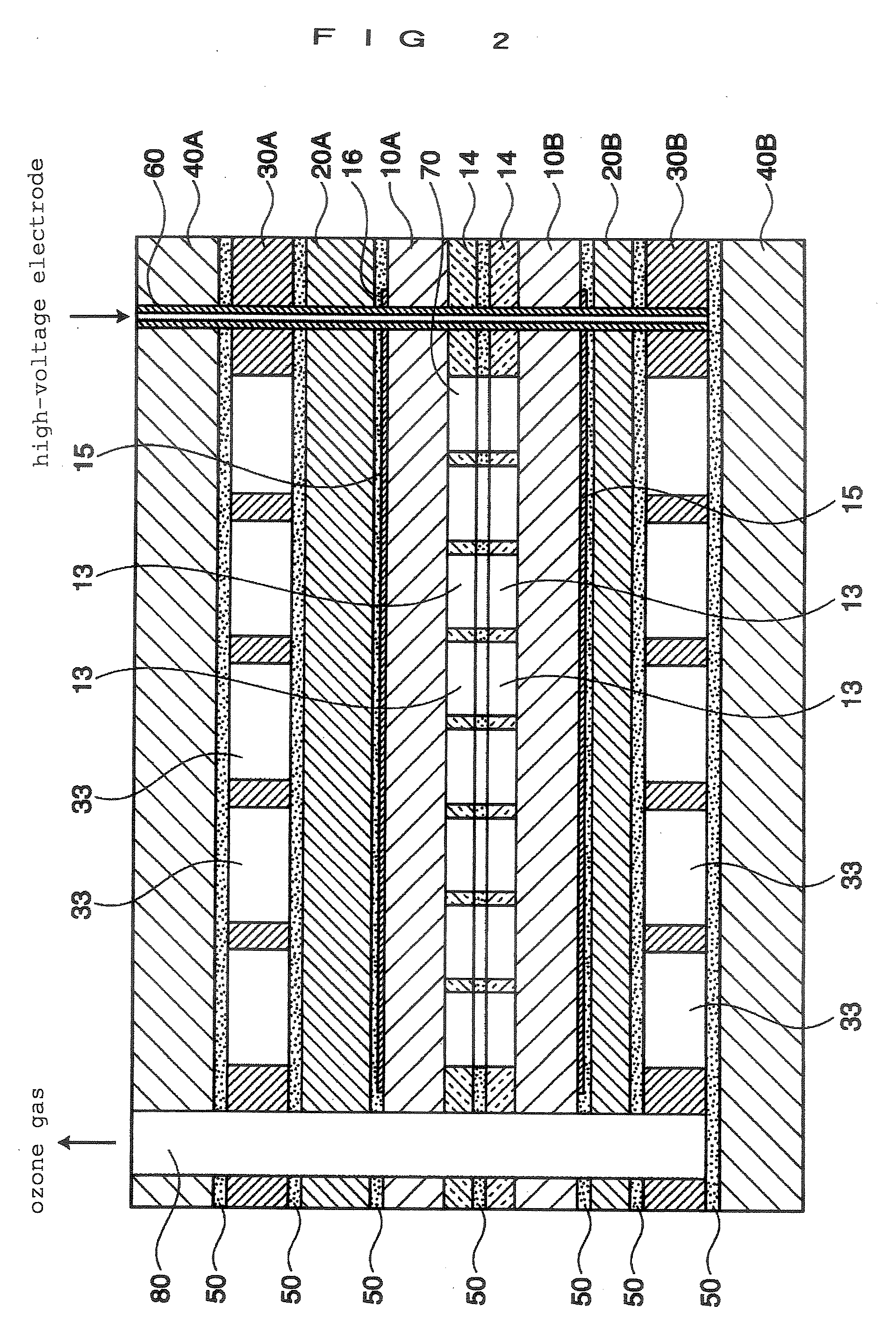
[0073] As a first example, the thickness of the high-voltage insulating plate 20A was variously changed in the discharge cell shown in FIGS. 1 and 2. Each thickness of the dielectric bodies 10A and 10B was set to 0.3 mm, and the total thickness was set to 0.6 mm. The gap amount in the discharge gap 70 was set to 35 μm, the thickness of the low-voltage insulating plate 20B was set to 0.3 mm, and each thickness of the slit plates 30A and 30B was set to 0.5 mm. The thickness of the high-voltage insulating plate 20A was set to 2 mm, 0.8 mm, and 0.3 mm, which was 3.3 times, 1.3 times and 0.5 times the total thickness (0.6 mm) of the dielectric bodies 10A and 10B, respectively.

[0074] The material gas was high-purity oxygen gas (6N), and a flow volume thereof was s...

second embodiment

[0082] Next, an effect of a surface roughness of the dielectric body in the discharge cell of the present invention on the ozone concentration is quantitatively indicated to clarify the effect of the present invention.

[0083] In the discharge cell shown in FIGS. 1 and 2, a roughness of the opposed surfaces of the dielectric bodies 10A and 10B was variously changed. The lapping finish was used as the mirror-like finishing to smooth the opposed surfaces, and the roughness was adjusted by changing a processing time. Without processing, the surface roughness Ra was 6.3 μm.

[0084] The dielectric bodies 10A and 10B were formed of TiO2-doped alumina, and each thickness was set to 0.3 mm. The gap amount in the discharge gap 70 was set to 70 μm, the thickness of the low-voltage insulating plate 20B was set to 0.3 mm, the thickness of the high-voltage insulating plate 20A was set to 0.8 mm, and each thickness of the slit plates 30A and 30B was set to 0.5 mm, respectively.

[0085] The material ...


PUM


Abstract

To enable to reduce a manufacturing cost and to generate high-concentration ozone gas, in a plate-type discharge cell for ozonizer. To improve ozone concentration without depending on reduction of a gap amount in a discharge gap. Dispose dielectric bodies between a high-voltage electrode and a low-voltage electrode to form a discharge gap. On a back surface side of the high-voltage and the low-voltage electrodes, a high-voltage insulating plate and a low-voltage insulating plate are disposed, respectively, for insulating the electrodes and from cooling water. A thickness of the high-voltage insulating plate is set to not less than 0.5 times and not more than 3.5 times the total thickness of the dielectric bodies, which are disposed between the high-voltage and the low-voltage electrodes. Opposed surfaces of the dielectric bodies, which contact the discharge gap, are smoothed such that a roughness Ra thereof is not larger than 2 μm.

Description

BACKGROUND OF THE INVENTION [0001] 1. Field of the Invention [0002] The present invention relates to a plate-type discharge cell used in an ozonizer. [0003] 2. Description of the Related Art [0004] Discharge cells used in an ozonizer are classified broadly into a plate-type and a tube-type, and the plate-type discharge cells are subdivided into a circular plate-type and a square plate-type. The square plate-type discharge cell is often used for generating highly concentrated ozone, because a discharge gap formed between a pair of plate-like dielectric bodies may easily be narrowed and a dimension of the discharge gap may easily be equalized in a plane. A typical structure of the plate-like discharge cell will be described below. [0005] Plate like dielectric bodies, each of which is formed of a square ceramic plate or the like, are disposed so as to be opposite to each other with a predetermined spacing therebetween. A pair of dielectric bodies have electrode layers, each of which is...

Claims


Application Information

Patent Timeline
Patent Type & Authority Applications(United States)
IPC IPC(8): B01J19/08
CPCC01B13/11C01B13/115C01B2201/12C01B2201/76C01B2201/34C01B2201/64C01B2201/32
Inventor MATSUNO, TAKASHI
Owner SUMITOMO PRECISION PROD CO LTD
Why Eureka
Try Eureka