
Prosthetic stent graft for treatment of abdominal aortic aneurysm

a technology for abdominal aortic aneurysms and prosthetic stents, which is applied in the field of prosthesis for the treatment of abdominal aortic aneurysms, can solve the problems of pre-existing aneurysms, uncontrollable hemorrhage, and bursting of aneurysms in developed nations, and achieves the effects of reducing the risk of aneurysms

Inactive Publication Date: 2007-07-05
CORDIS CORP
View PDF14 Cites 90 Cited by
  • Summary
  • Abstract
  • Description
  • Claims
  • Application Information

AI Technical Summary

Benefits of technology

"The present invention provides a prosthetic stent graft with a trunk and two legs that have a bifurcated vascular graft supported by stent sections. The flow channels have a taper angle to decrease in cross-sectional area along their length between the bifurcation point and an outlet. The stent graft is designed to be deployed in the abdominal aorta of a patient to treat abdominal aortic aneurysm. The technical effects of the invention include improved blood flow and reduced risk of complications during surgery."

Problems solved by technology

Vascular disease is a leading cause of premature mortality in developed nations, often presenting as a vascular aneurysm.
If untreated, the aneurysm may burst and hemorrhage uncontrollably.
Aneurysms are particularly dangerous and prevalent in the aorta, because the aorta supplies blood to all other areas of the body, and because the aorta is subject to particularly high pressures and stresses accordingly.
Designing a viable stent graft for the treatment of abdominal aortic aneurysm (AAA) is particularly challenging, in part because the graft must branch to follow the shape of the abdominal aorta to carry blood into the separate iliac arteries without obstruction.

Method used


Image

  • Prosthetic stent graft for treatment of abdominal aortic aneurysm
  • Prosthetic stent graft for treatment of abdominal aortic aneurysm
  • Prosthetic stent graft for treatment of abdominal aortic aneurysm

Examples


Embodiment Construction

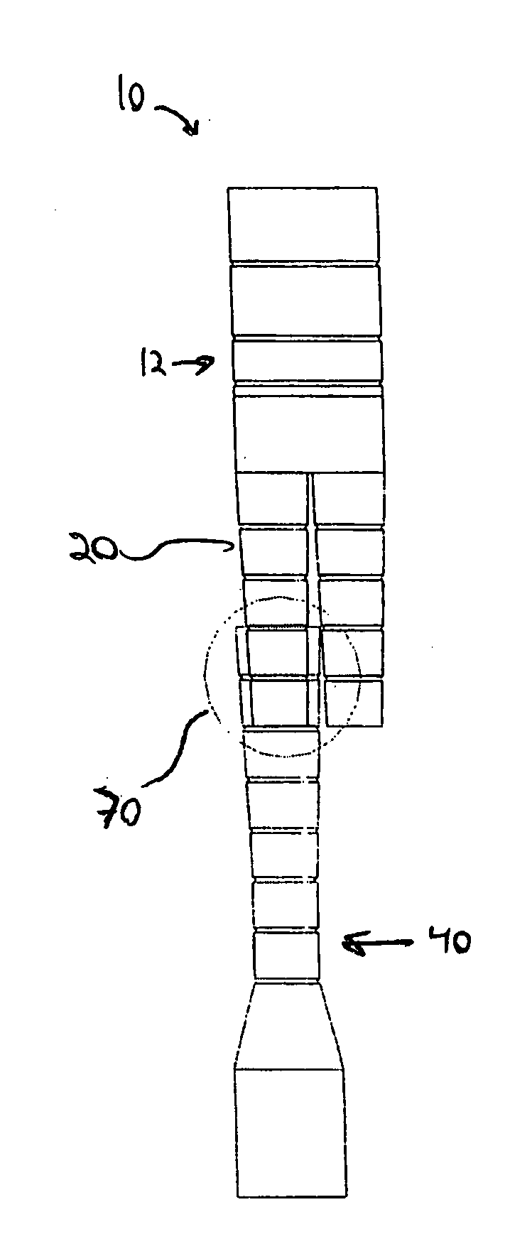
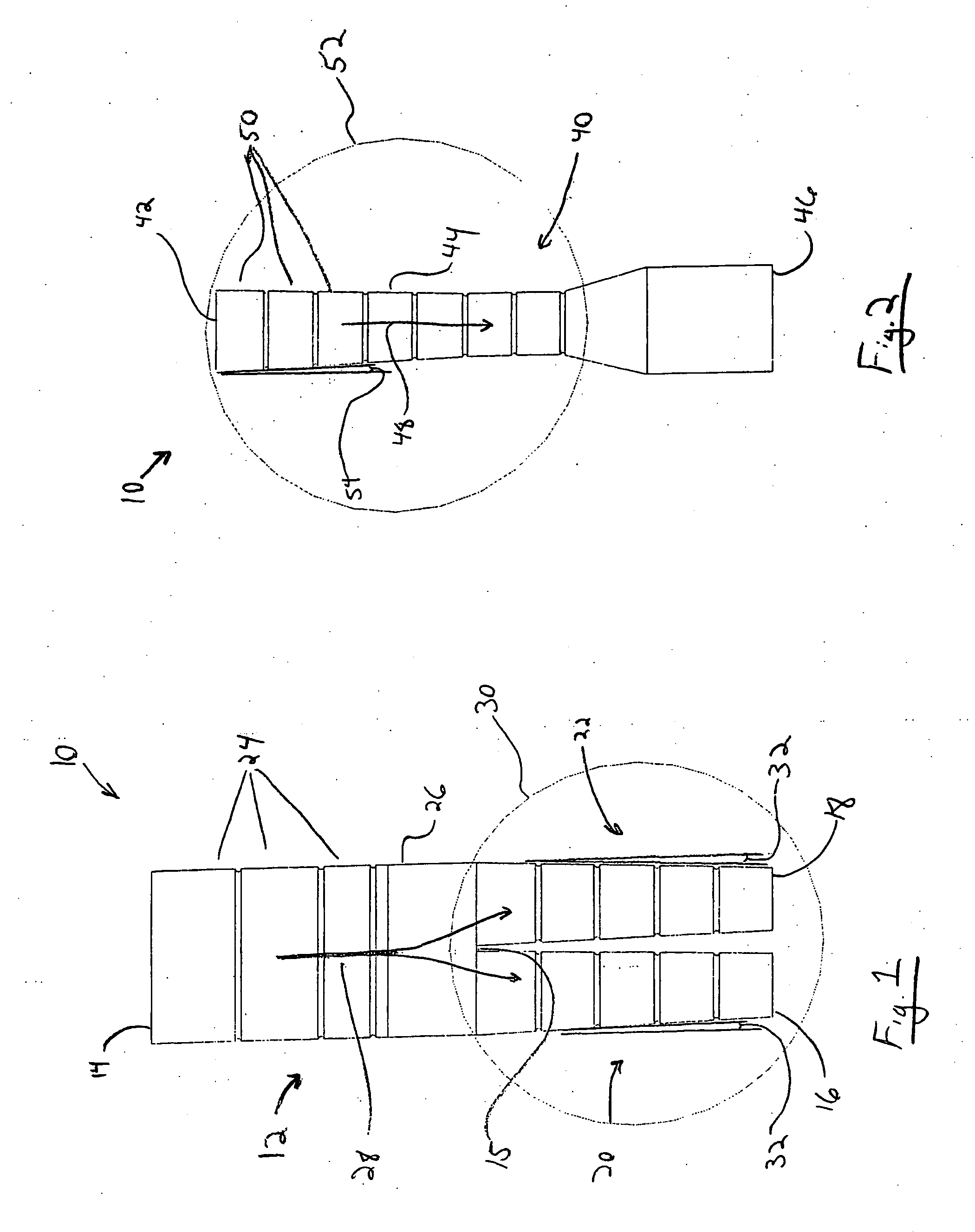
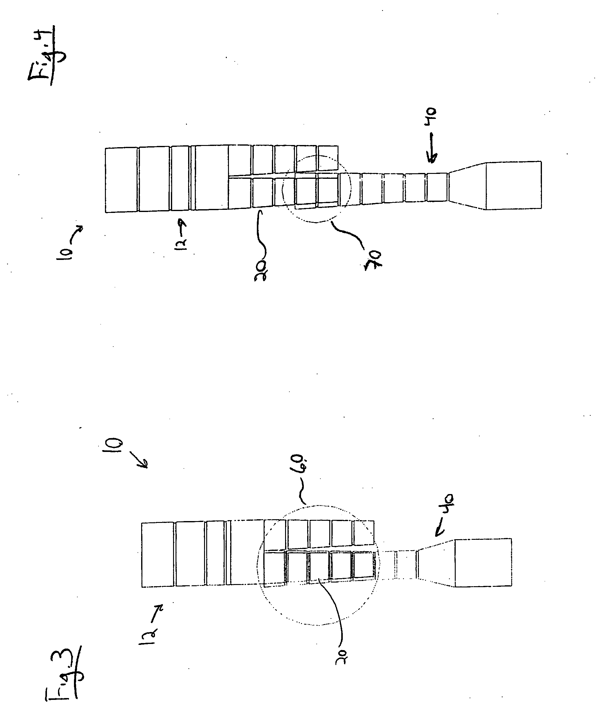
[0018]Referring now to FIGS. 1 and 2, illustrated are two components of stent graft, generally 10, according to the present invention. Trunk section 12 has a substantially circular inlet 14 at one end, and two substantially circular outlets 16, 18, at an opposite end. Inlet and outlet are derived from the intended direction of blood flow, indicated by arrow 28, through the trunk section 14 when positioned in the abdominal aorta and iliac arteries of a patient. The trunk section 12 bifurcates at point 15 between inlet 14 and outlets 16, 18 into two flow channels, 20, 22, respectively. Preferably, the trunk section 12 is comprised of plural stent segments 24 along its length, secured to and joined by a vascular graft 26 which surrounds the segments 24 and defines the flow through the trunk section 12. However, a unitary stent structure may be used as well, in addition to more or fewer segments 24 of varying length than shown in this exemplary embodiment. In a preferred embodiment, ste...


PUM


Abstract

A prosthetic stent graft including a trunk with a vascular graft bifurcated into two flow channels. The flow channels have a first taper angle, decreasing area along its length between the bifurcation point and an outlet. A leg section of the stent graft includes a tubular vascular graft. An inlet of the leg section has a deployed diameter at least about the same size or larger than a deployed diameter of the outlet of the flow channels. The leg section has its own taper angle, preferably less than or about equal to, and more preferably about equal to the taper angle of the flow channel. The deployed diameter of the leg section inlet is preferably about the same size or larger than the deployed diameter of the flow channels adjacent the bifurcation point of the trunk section, and the deployed diameter of flow channel outlets are preferably about the same size or smaller than the deployed diameter of the leg section at an equal distance from the leg section inlet as the outlet is from bifurcation point. Also provided according to the present invention is a method of in situ stent graft sizing for the treatment of abdominal aortic aneurysm.

Description

BACKGROUND OF THE INVENTION[0001]1. Field of Invention[0002]The invention relates to the field of medical devices, and more specifically to a prosthesis for the treatment of vascular disease, particularly abdominal aortic aneurysm.[0003]2. Description of Related Art[0004]Vascular disease is a leading cause of premature mortality in developed nations, often presenting as a vascular aneurysm. A vascular aneurysm is a localized dilation of a vessel wall, due to thinning or weakness of the wall structure, or separation between layers of the vessel wall. If untreated, the aneurysm may burst and hemorrhage uncontrollably. Aneurysms are particularly dangerous and prevalent in the aorta, because the aorta supplies blood to all other areas of the body, and because the aorta is subject to particularly high pressures and stresses accordingly. Rupture of an aortic aneurysm is the 15th leading cause of death the United States, afflicting 5% of older men.[0005]Aortic aneurysms are described by th...

Claims


Application Information

Patent Timeline
Patent Type & Authority Applications(United States)
IPC IPC(8): A61F2/06A61F2/94
CPCA61F2/07A61F2002/067A61F2230/0078A61F2/89A61F2250/0039
Inventor MAJERCAK, DAVID C.PARK, JIN S.
Owner CORDIS CORP
Learn More