Apparatus for reducing the diameter of a stent

a technology of stent and stent body, which is applied in the field of stent diameter reduction apparatus, can solve the problems of inability to achieve consistent, difficult to achieve a consistent, and inability to tailor individual length portions, etc., and achieve the effect of reducing the diameter of the stent and reducing the diameter of the desired individual length portion

Inactive Publication Date: 2007-07-12
QUALIMED INNOVATIVE MEDIZINPROD
View PDF4 Cites 1 Cited by
  • Summary
  • Abstract
  • Description
  • Claims
  • Application Information

AI Technical Summary

Benefits of technology

[0008] Originating from the state of the art, the invention is based on the object to provide an apparatus for reducing the diameter of a stent which ap

Problems solved by technology

Errors as a result of human inadequacy cannot be avoided hereby.
As stents are typically placed upon catheters and the stents as well as the catheters have tolerances, it becomes difficult to attain a consistent result, each time the diameter of a stent is to be reduced (crimped).
It is

Method used


Image

  • Apparatus for reducing the diameter of a stent
  • Apparatus for reducing the diameter of a stent
  • Apparatus for reducing the diameter of a stent

Examples


Embodiment Construction

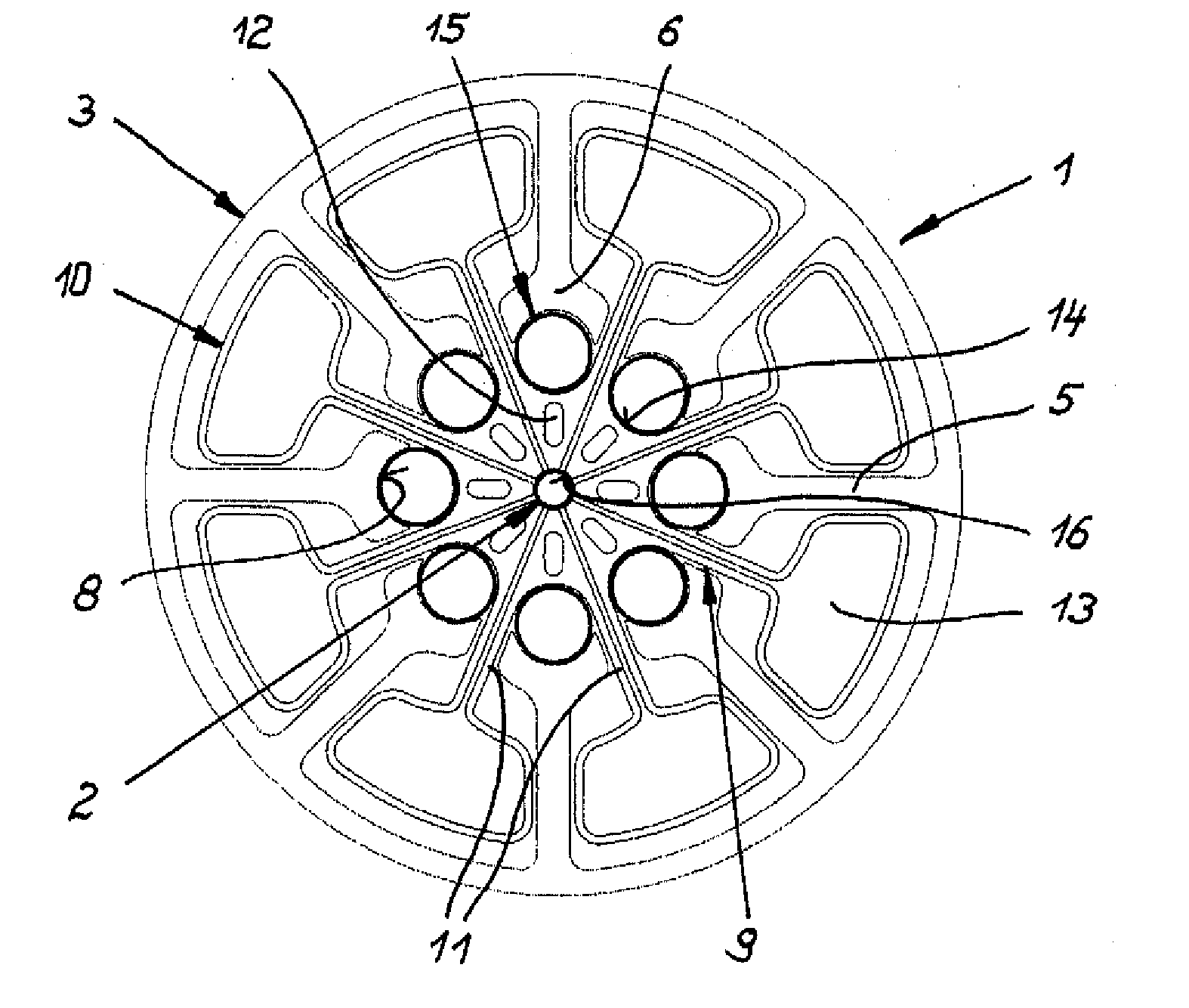
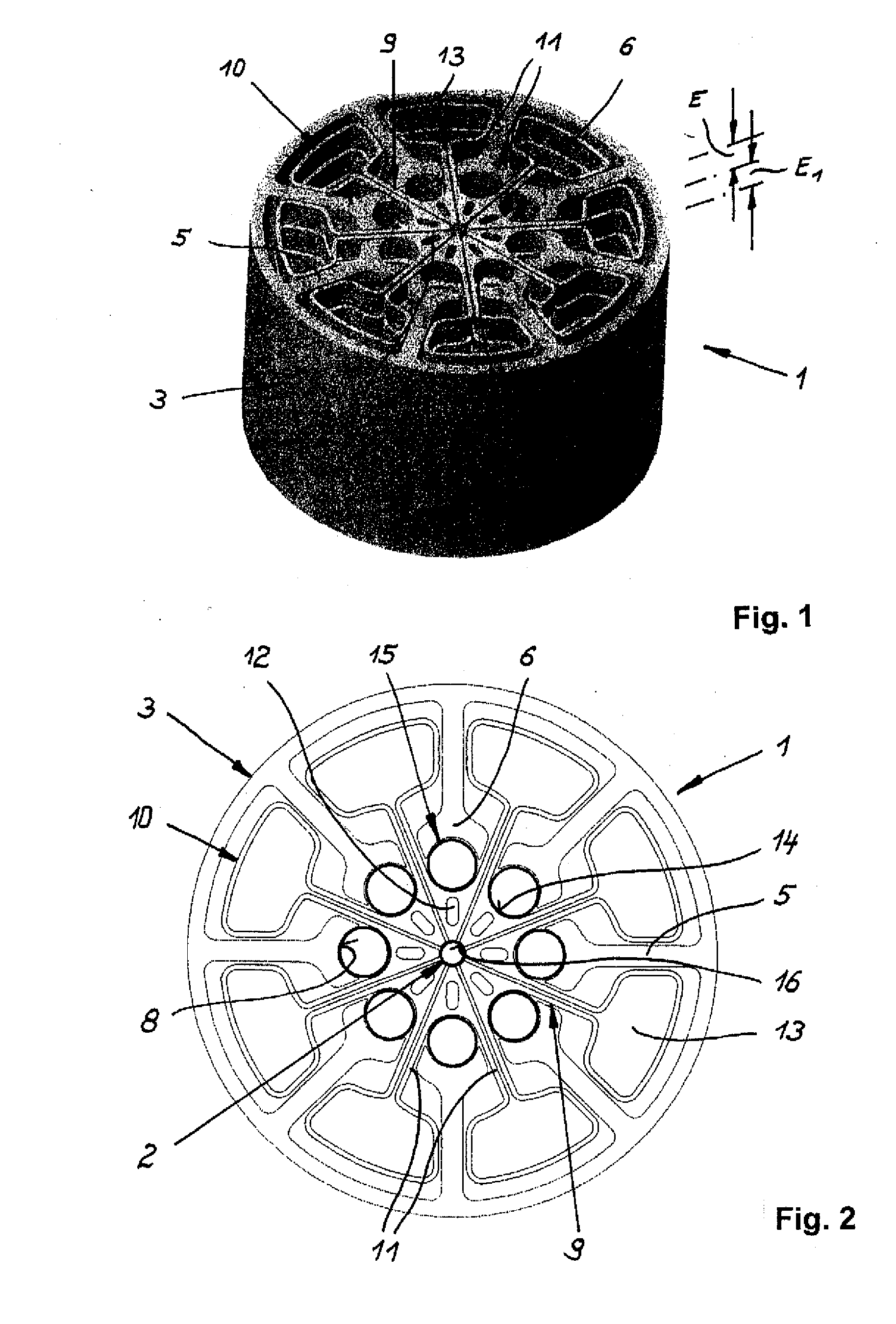
[0034] An apparatus for reducing the diameter of a stent 2, not shown in greater detail, is labeled in FIGS. 1 and 2 with 1.

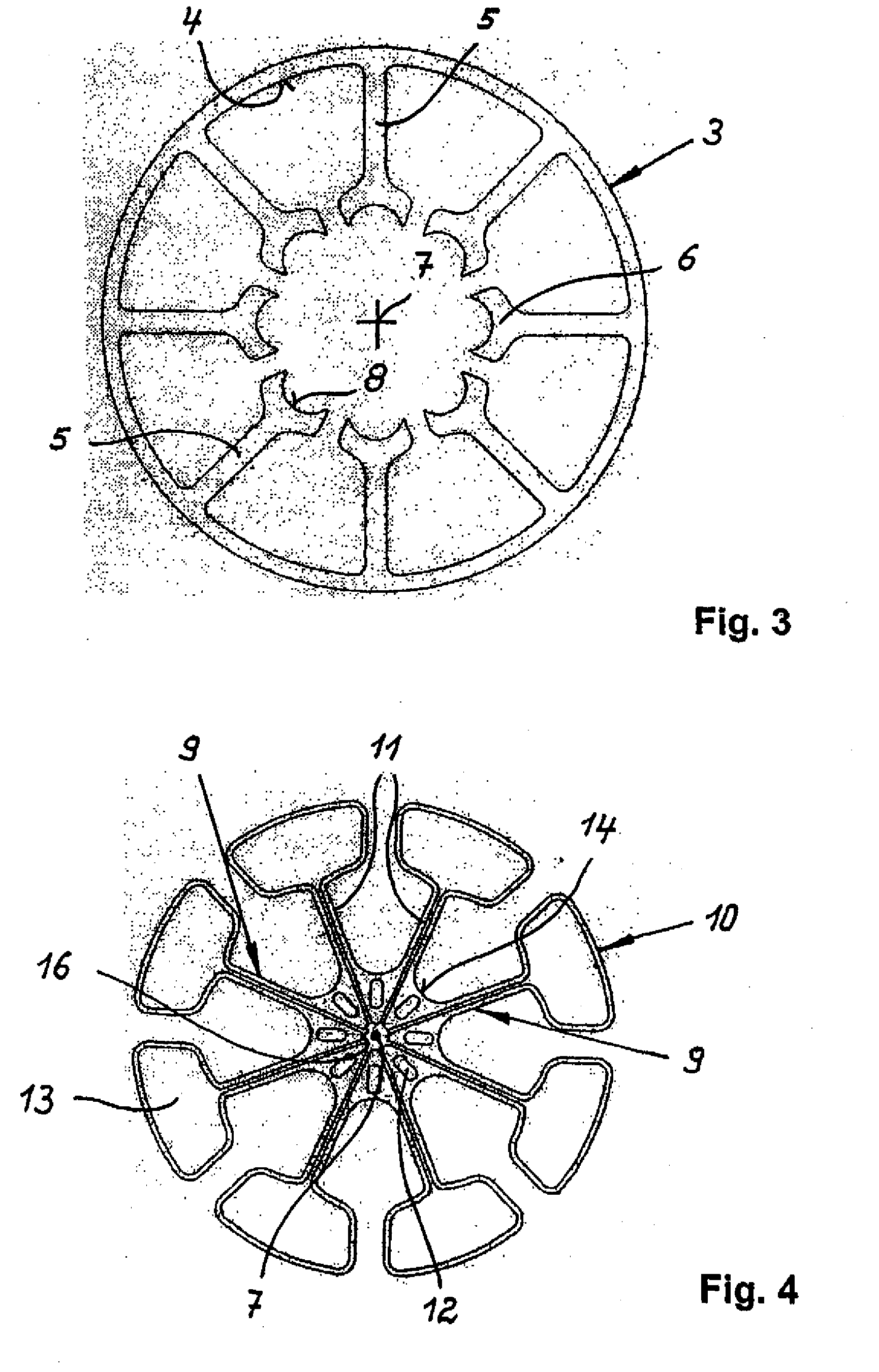
[0035] According to FIGS. 1 to 3, the apparatus includes a cylindrical abutment 3 of steel. Extending radially inwards from the inner surface 4 of the abutment 3 are struts 5 which have open concave cylinder segment like resistance surfaces 8 at the inner wider end 6 toward the center axis 7.

[0036] As can be seen in FIGS. 1 to 3, the abutment 3 with the struts 5 is coupled with segmental compressors 9 by being moved axially into one another (FIGS. 1, 2 and 4) which form components of a spring band 10 extending in the form of a meander in circumferential direction. The compressors 9 have legs 11 diverging from the center axis 7. Adjacent to the center axis 7, the compressors 9 are strengthened by material and provided with oblong holes 12. The neighboring legs 11 of each two compressors 9 merge at the radially outer ends into trapezoidal zones 13 which, as can...


PUM

PropertyMeasurementUnit
Forceaaaaaaaaaa
Pressureaaaaaaaaaa
Diameteraaaaaaaaaa

Abstract

The apparatus (1a) for reducing the diameter of a stent (2) includes compressors (9a) which are supported on a circumferential abutment (3a) and act, at least indirectly, radially on the outer surface of the stent (2). Resiliently elastic tensioning members (15) are provided between the radially inwardly displaceable segmental compressors (9a) and the abutment (3a) and can be acted upon by a pressure fluid in opposition to a resiliently elastic rebound force (21).

Description

BACKGROUND OF THE INVENTION [0001] The invention relates to an apparatus for reducing the diameter of a stent. [0002] Such an apparatus belongs to the state of the art in view of the DE 297 14 857 U1. It includes a clamping tongs with arms movable relative to one another and configured with conical openings. The openings expand towards the central transverse plane of the clamping tongs. [0003] The apparatus further includes a shaping body for a stent which can be received in the openings of the clamping tongs, i.e. the stent includes a short central portion, which is continued by two conically descending portions in a direction of the end surfaces, and two cylindrical end portions. The shaping body has a central passageway for receiving a stent. [0004] The shaping body is subdivided in radial direction by several longitudinally extending slots to define interconnected compressors. The cross section of the compressors is wedge-shaped, with the compressors narrowing in a direction of ...

Claims


Application Information

Patent Timeline
IPC IPC(8): B21D39/00
CPCA61F2/95Y10T29/49913B25B27/10A61F2002/9522A61F2/9522
Inventor NISSL, THOMAS
Owner QUALIMED INNOVATIVE MEDIZINPROD
Why Eureka
Try Eureka