Motorized mount for electronic display

a motorized mount and electronic display technology, applied in the direction of machine supports, building scaffolds, other domestic objects, etc., can solve the problems of occupying floor space, prone to tipping, heavy and difficult for an individual to manage the electronic display on the flat panel, etc., and achieve good structural strength characteristics

Inactive Publication Date: 2007-07-12
LEGRAND AV INC
View PDF22 Cites 39 Cited by
  • Summary
  • Abstract
  • Description
  • Claims
  • Application Information

AI Technical Summary

Benefits of technology

[0008] The present invention addresses the need of the industry for a flat panel display mount that exhibits good structural strength characteristics in a relatively lightweight and compact form, and that enables remotely controlled positioning of the display with a smooth motion. In embodiments of the invention, a motorized mount includes a wall interface assembly and a display device interface operably coupled by a scissor arm assembly. The scissor arm assembly is compounded for strength, each arm comprising two parallel arms. One end of one compounding arm of the scissor arm assembly is coupled to a positioning member threadedly engaged with a vertical screw in the wall interface driven by a motor, which the other end is pivoted to the display interface. One end of the other compounding arm is slidably received on a vertical shaft on the display interface, while the other end of the same arm is pivoted to the wall interface. When the motor is actuated, the positioning block is moved up or down on the screw, thereby causing the display interface to be moved closer to or away from the wall by the scissor arm assembly in a generally horizontal plane. A second positioning motor may be attached to the scissor arm assembly and coupled to the display interface through a geared arrangement to enable side-to-side rotation of the display interface about the shaft axis. Each motor may be remotely controlled using known remote control systems, including wired and wireless control systems.

Problems solved by technology

In very large screen sizes, however, even flat panel electronic displays are heavy and difficult for an individual to manage.
While this may be accomplished in some instances by mounting the display on a wheeled cart, this approach has drawbacks.
One problem with such an approach is that the large mass of the flat panel display may make the combination top-heavy and prone to tipping.
Another drawback is that the cart takes up floor space, thereby negating part of the space advantage of a flat panel display.
Moreover, for full positioning capability, the cart must be remotely positionable as well as the display itself, making for a relatively complex position control system.
These prior devices, however, have certain drawbacks.
A drawback of this device, however, is the display device causes relatively large structural loads to be placed on the threaded rods, tubes and linear actuators when the display is cantilevered a significant distance from the wall.
The size of these elements must be made correspondingly large to accommodate this loading, adding to the space demands, weight, and cost of the mounting device.
Further, the device requires a relatively large number of actuators or motors, adding to the cost of the device and complexity of the control systems.
A drawback of this device, however, is that a relatively complex control system is needed to monitor and control the multiple positioning motors.
Further, even with such a complex control system, the resulting positioning movement of the display is likely to be somewhat non-uniform and halting due to the need to assimilate position feedback signals in the control system.

Method used


Image

  • Motorized mount for electronic display
  • Motorized mount for electronic display
  • Motorized mount for electronic display

Examples


Embodiment Construction

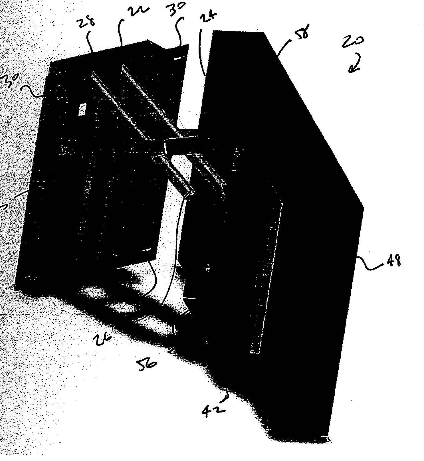
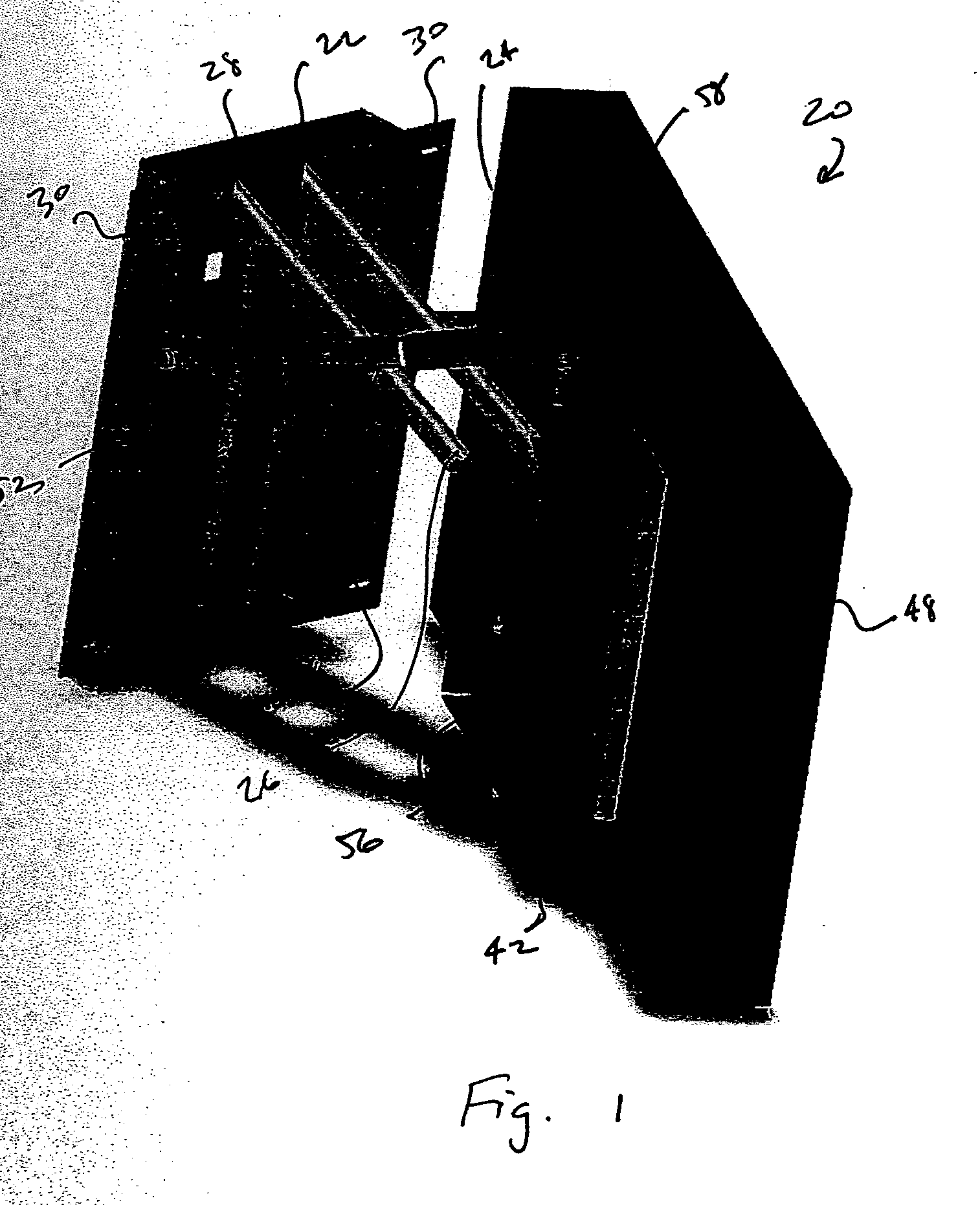
[0022] A motorized mount according to an embodiment of the present invention is depicted generally at 20 in the figures. Motorized mount 20 generally has three major components: wall interface assembly 22, display device interface 24 and positioning assembly 26, as depicted in FIGS. 1 and 6.

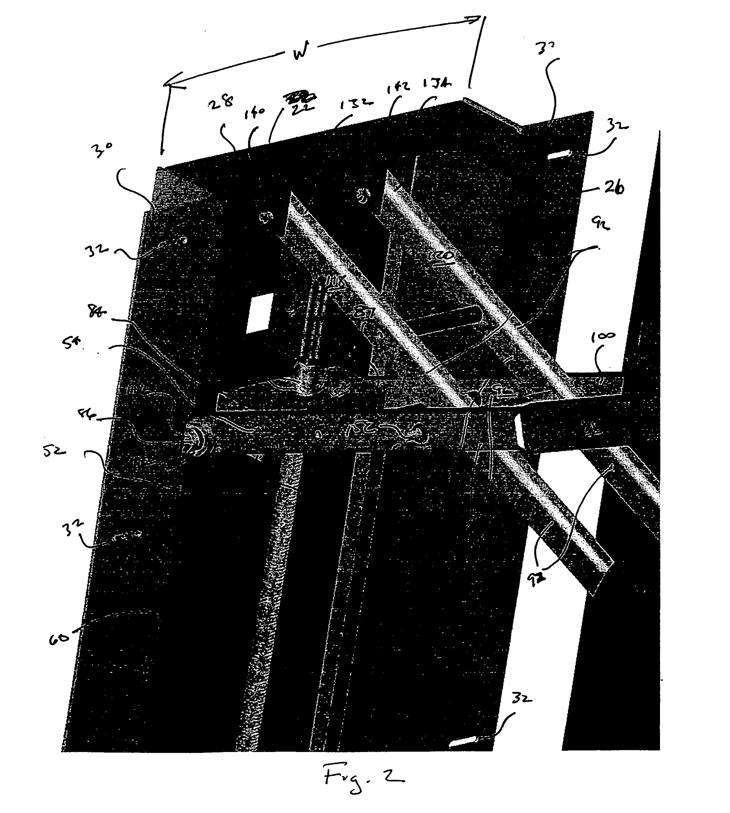
[0023] The first component of motorized mount 20 is wall interface assembly 22, shown particularly in FIGS. 2, 3, 7, 11 and 12. Wall interface assembly 22 generally includes housing 28 having a pair of laterally projecting flanges 30. Housing 28 may have a width dimension W (see FIG. 2) defined between the flanges 30 and selected so as to correspond with the spacing between adjacent studs of standard stud spacing in frame wall construction such stud spacing is, for example, 16 inches or 24 inches on center. Each flange 30 may have one or more apertures 32 for receiving fasteners 34 (see FIG. 11) to attach wall interface assembly 22 to studs 36 in a wall 38. Mechanism cover 40 (see FIG. 12) may b...


PUM


Abstract

A motorized mount for an electronic display includes a biaxially shiftable mount assembly including a positioning assembly being translatably shiftable in a plane and a rotator assembly operably coupled to the positioning assembly, the rotator assembly being rotatably shiftable about an axis, the axis being orthogonally disposed relative to the plane. A method of selectively positioning an electronic display is further included.

Description

RELATED APPLICATION [0001] The present application claims the benefit of U.S. Provisional Application 60 / 755811, filed Jan. 3, 2006, and incorporated herein in its entirety by reference.FIELD OF THE INVENTION [0002] The present invention relates to mounting devices for electronic displays, and in particular, remotely selectively positionable mounting devices for flat panel electronic display devices. BACKGROUND OF THE INVENTION [0003] Flat panel electronic display devices such as flat panel televisions and display monitors are becoming increasingly popular due to superior image quality, space utilization, and increasing affordability as compared with conventional CRT displays. These flat panel display technologies have proven especially well suited to screen sizes over 36 inches, above which the size and weight of a CRT device become prohibitive. [0004] In very large screen sizes, however, even flat panel electronic displays are heavy and difficult for an individual to manage. Furth...

Claims


Application Information

Patent Timeline
Patent Type & Authority Applications(United States)
IPC IPC(8): E04G3/00
CPCF16M11/08F16M11/18F16M2200/061F16M13/02F16M11/38
Inventor DITTMER, JAYGILL, SCOTT
Owner LEGRAND AV INC
Why Eureka
Try Eureka