Method for Forming Self-Aligned Thermal Isolation Cell for a Variable Resistance Memory Array

a technology of variable resistance and thermal isolation cell, which is applied in the direction of digital storage, semiconductor devices, instruments, etc., can solve the problems of manufacturing such devices with very small dimensions

Active Publication Date: 2007-07-12
MACRONIX INT CO LTD
View PDF98 Cites 237 Cited by
  • Summary
  • Abstract
  • Description
  • Claims
  • Application Information

AI Technical Summary

Problems solved by technology

Problems have arisen in manufacturing such devices with very small dimensions, and with variations in process that meets tight specifications needed for large-scale memory devices.

Method used


Image

  • Method for Forming Self-Aligned Thermal Isolation Cell for a Variable Resistance Memory Array
  • Method for Forming Self-Aligned Thermal Isolation Cell for a Variable Resistance Memory Array
  • Method for Forming Self-Aligned Thermal Isolation Cell for a Variable Resistance Memory Array

Examples


Embodiment Construction

[0014]The following detailed description is made with reference to the figures. Preferred embodiments are described to illustrate the present invention, not to limit its scope, which is defined by the claims. Those of ordinary skill in the art will recognize a variety of equivalent variations on the description that follows.

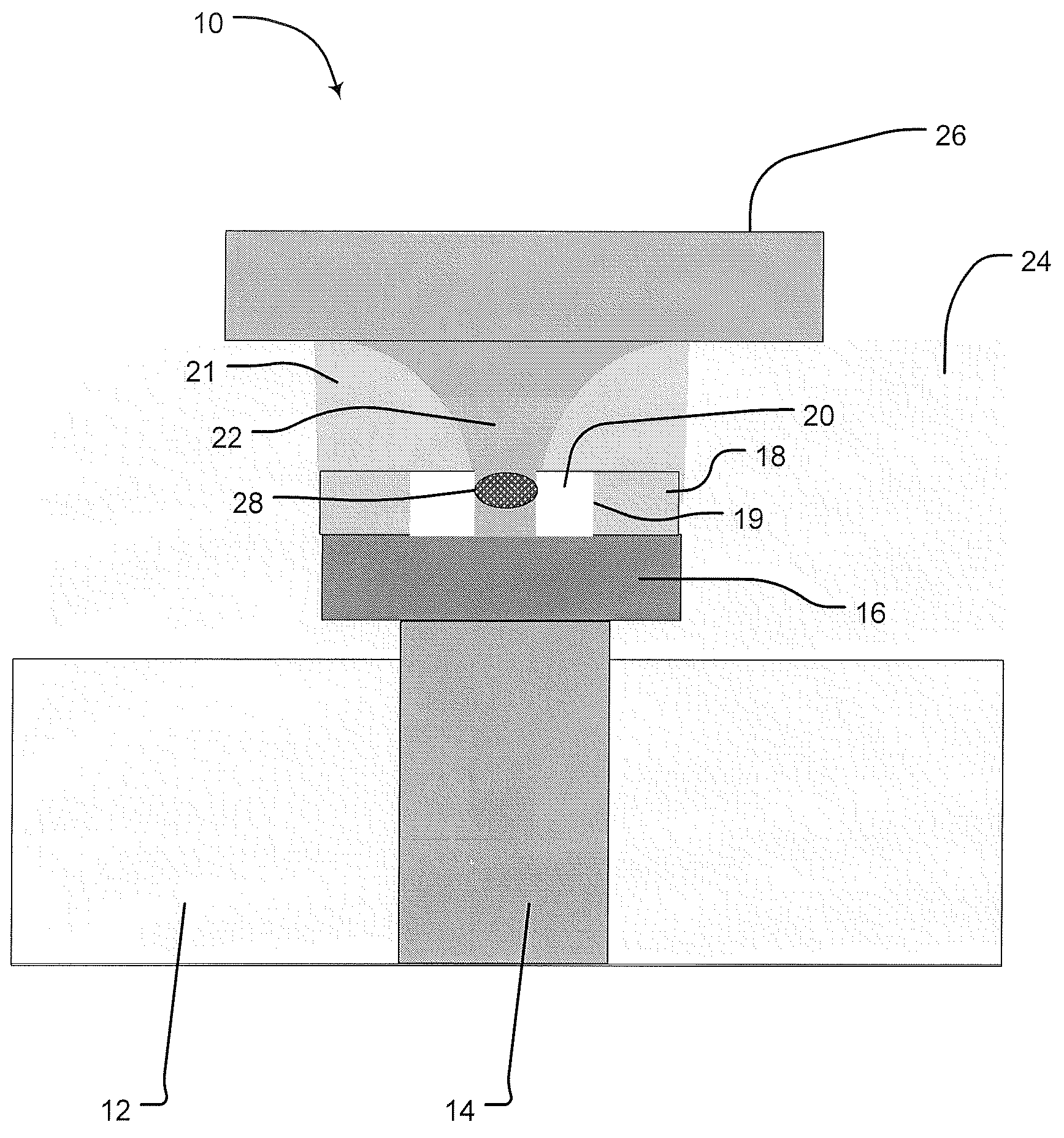
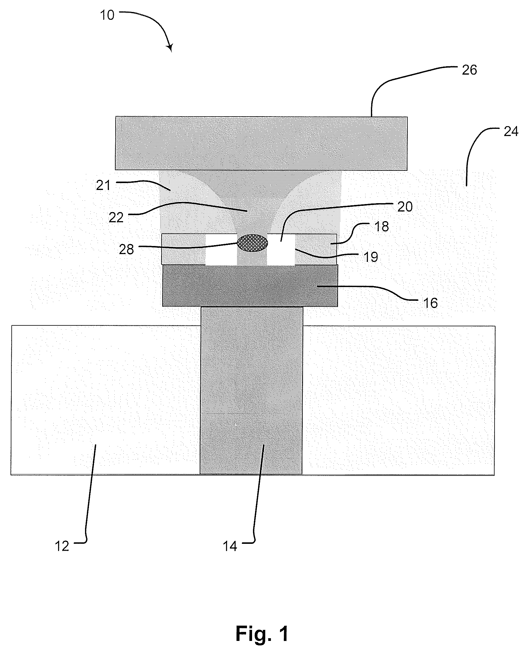
[0015]A memory element 10 is illustrated in FIG. 1. The element is fabricated on a substrate, or inter-layer dielectric layer, 12. The following discussion sets out the structure of this element, with the fabrication process following shortly thereafter. This layer preferably consists of silicon oxide or a well-known alternative thereto, such as a polyimide, silicon nitride or other dielectric fill material. In embodiments, the dielectric layer comprises a relatively good insulator for heat as well as for electricity, providing thermal and electrical isolation. An electrical contact, or plug, 14, preferably formed from a refractory metal such as tungsten, is form...


PUM


Abstract

A non-volatile method with a self-aligned RRAM element. The method includes a lower electrode element, generally planar in form, having an inner contact surface. At the top of the device is a upper electrode element, spaced from the lower electrode element. A containment structure extends between the upper electrode element and the lower electrode element, and this element includes a sidewall spacer element having an inner surface defining a generally funnel-shaped central cavity, terminating at a terminal edge to define a central aperture; and a spandrel element positioned between the sidewall spacer element and the lower electrode, having an inner surface defining a thermal isolation cell, the spandrel inner walls being spaced radially outward from the sidewall spacer terminal edge, such that the sidewall spacer terminal edge projects radially inward from the spandrel element inner surface. ARRAM element extends between the lower electrode element and the upper electrode, occupying at least a portion of the sidewall spacer element central cavity and projecting from the sidewall spacer terminal edge toward and making contact with the lower electrode. In this manner, the spandrel element inner surface is spaced from the RRAM element to define a thermal isolation cell adjacent the RRAM element.

Description

REFERENCE TO RELATED APPLICATION[0001]This application claims the benefit of U.S. Provisional Patent Application No. 60 / 754,161, entitled “Method for Forming Self-Aligned Thermal Isolation Cell for a Phase Change Memory Array” filed on 27 Dec. 2005. That application is incorporated by reference for all purposes.BACKGROUND OF THE INVENTION[0002]1. Field of the Invention[0003]The present invention relates to non-volatile memory structures, and more specifically to memory devices employing Resistance Random Access Memory (RRAM) memory elements.[0004]2. Description of Related Art[0005]RRAM based memory materials are widely used in read-write optical disks and non-volatile memory arrays. These materials have at least two solid phases, including for example a generally amorphous solid phase and a generally crystalline solid phase. Laser pulses are used in read-write optical disks to switch between phases and to read the optical properties of the material after the RRAM.[0006]RRAM based me...

Claims


Application Information

Patent Timeline
Patent Type & Authority Applications(United States)
IPC IPC(8): H01L47/00
CPCH01L45/06H01L45/1233H01L45/1683H01L45/144H01L45/1293H10N70/231H10N70/8616H10N70/826H10N70/8828H10N70/066
Inventor LAI, ERH-KUNHO, CHIAHUAHSIEH, KUANG YEU
Owner MACRONIX INT CO LTD
Why Eureka
Try Eureka