Contact lens

a technology of contact lenses and lenses, applied in the field of contact lenses, can solve the problems of difficult manufacturing of contact lenses, difficult to achieve good wear comfort, mold machining, etc., and achieve the effect of easy manufacturing of objective contact lenses, good operability, and excellent precision

Inactive Publication Date: 2007-07-12
MENICON CO LTD
View PDF8 Cites 42 Cited by
  • Summary
  • Abstract
  • Description
  • Claims
  • Application Information

AI Technical Summary

Benefits of technology

[0025] According to the method of the present invention, a mold for a forming die to produce the contact lens of novel structure constructed according to any of the first to seventh modes of the invention described previously may be machined easily by forming the entire cavity-forming face through a lathe turning process by turning about a single axis. Consequently, it is possible to readily manufacture the objective contact lens with excellent precision and with good operability in the entire process, including mold fabrication.
[0026] In particular, the entire zone of the lens front surface (including the optical portion and the peripheral portion) of the objective contact lens is of concentric circle shape centered on the lens geometrical center axis, when fabricating the mold for the forming die used for molding the contact lens. This makes it possible for the entire cavity-forming face to be formed through a lathe turning process by turning about a single axis, and conseq...

Problems solved by technology

However, contact lenses that employ a ballast mechanism have the problem of being too thick on the lower side, making it difficult to achieve good wear comfort.
As a result of which there arises the problem that mold machining, and hence manufacture of the ...

Method used


Image

  • Contact lens
  • Contact lens
  • Contact lens

Examples


Embodiment Construction

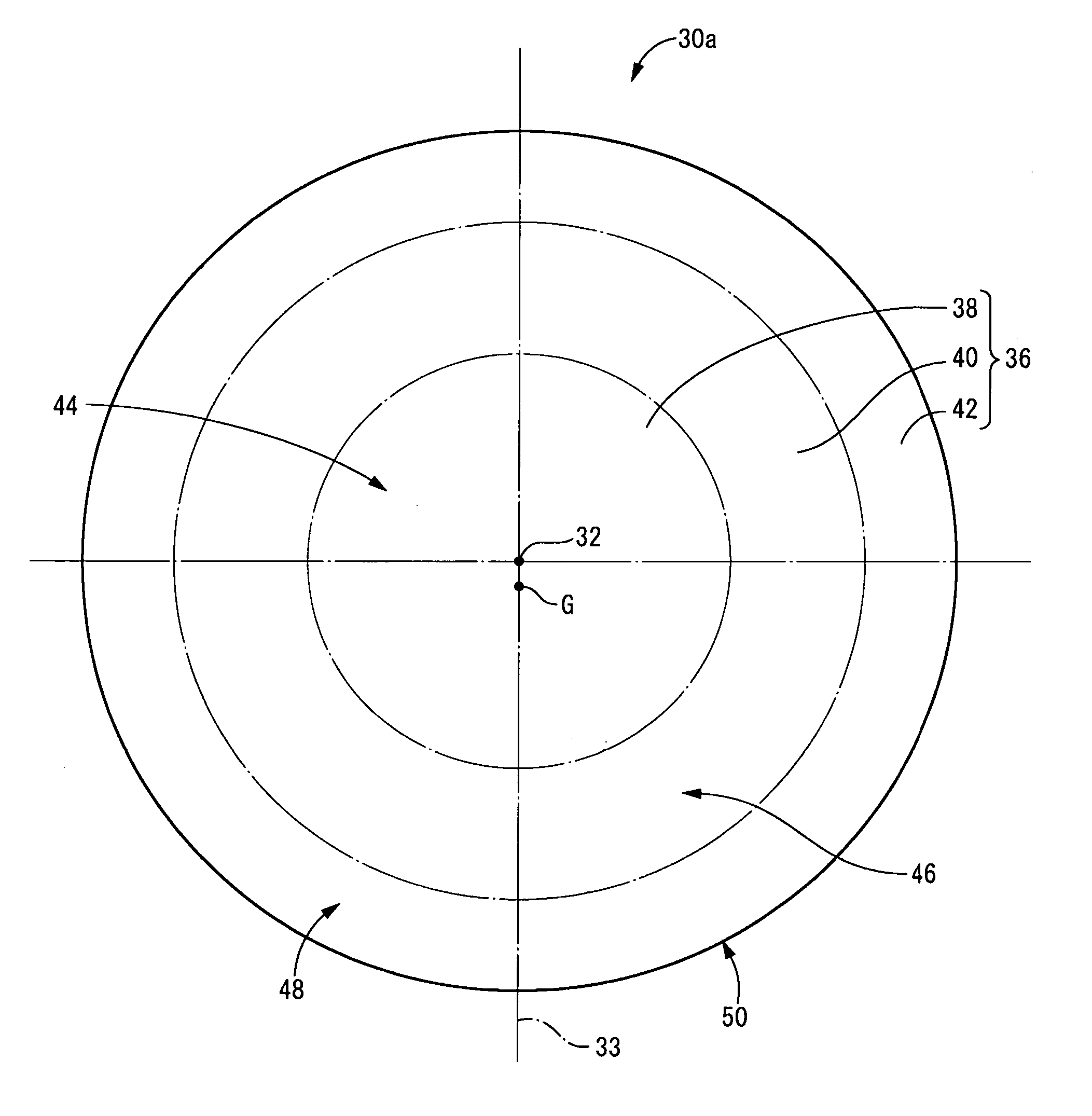
[0042] A more detailed understanding of the invention will be provided through the following description of the embodiments. In the description hereinbelow, as a general role, the term vertical direction shall be used in reference to the approximately vertical direction of the contact lens during wear, which is also the vertical direction in FIG. 1.

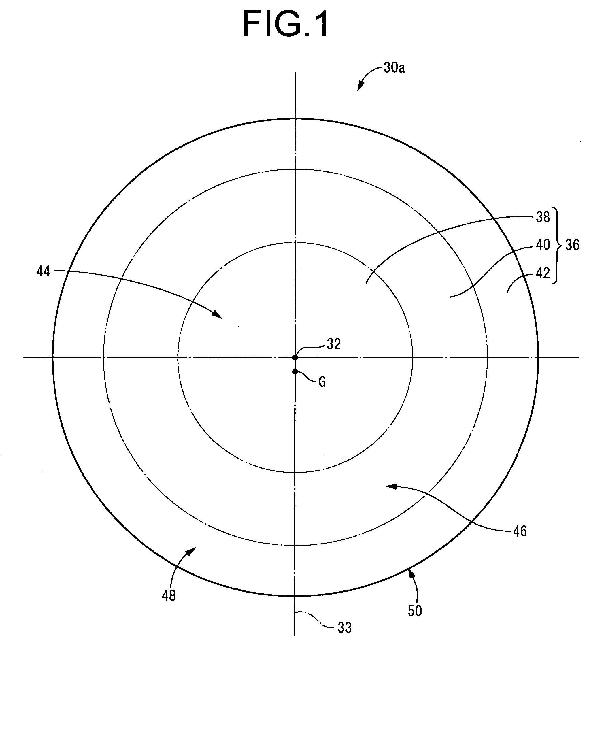
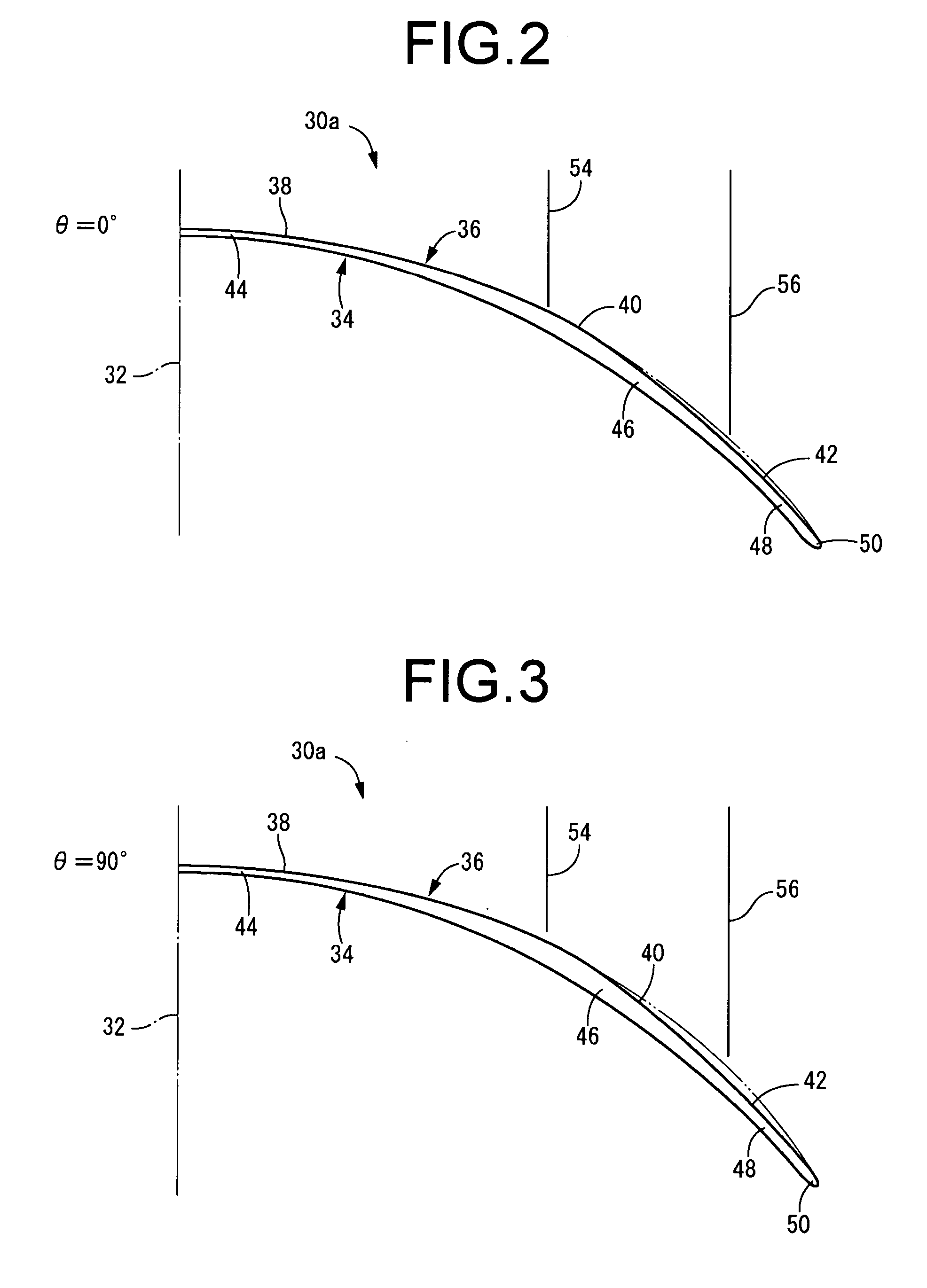
[0043] First, a specific example of a contact lens 30a of structure according to the invention will be described with reference to FIGS. 1-4. The contact lens 30a has a partial generally spherical shell shape overall. As is commonly known, the contact lens 30a is used by wearing it on the corneal surface of the eye. The contact lens 30a of this embodiment is symmetrical in shape in relation to a single diametrical line 33 passing through the lens geometrical center axis 32 which is the center axis of the lens contour, and is endowed with a ballast mechanism such that this diametrical line 33 is generally coincident with the vertical dire...


PUM


Abstract

An easy-to manufacture contact lens exhibiting an excellent axial stability and having a novel ballast mechanism. On the front surface (36) of the contact lens (30), (i) a circular front surface (38) forming an optical portion (44) and (ii) annular front surfaces (40, 42) forming peripheral portions (46, 48) are formed with a substantially constant radial dimension around the geometrical center axis (32) of the lens in the front view thereof. Cross-sectional shapes of the front surfaces (40, 42) at the peripheral parts are varied in the circumferential direction and the thickness at the peripheral portions (46, 48) is varied in the circumferential direction, thus shifting the center of gravity G of the contact lens (30) from the geometrical center axis (32) of the lens.

Description

TECHNICAL FIELD [0001] The present invention relates generally to contact lenses including both soft and hard types, and more particularly to a contact lens having a ballast mechanism for positioning the lens in the circumferential direction during wear. BACKGROUND ART [0002] Some contact lenses need to be positioned in the circumferential direction during wear, such as when the lens has an optical portion for correcting astigmatism, for example. Ballast mechanisms have been proposed as one type of method for positioning the lens in the circumferential direction during wear (see JP-B-60-24924, for example). A ballast mechanism involves setting the center of gravity of the lens so as to be off-center from the geometric center axis of the lens, so that the contact lens is positioned in the circumferential direction by utilizing the action of gravity on the contact lens. However, contact lenses that employ a ballast mechanism have the problem of being too thick on the lower side, makin...

Claims


Application Information

Patent Timeline
IPC IPC(8): G02C7/04
CPCG02C7/048G02C7/04G02C7/044G02C2202/04
Inventor HIBINO, SHINGOYAMASHITA, KEIJI
Owner MENICON CO LTD
Why Eureka
Try Eureka