Fault Detection Mechanism for LED Backlighting

a technology of led backlighting and fault detection, which is applied in the direction of static indicating devices, emergency protective arrangements for limiting excess voltage/current, instruments, etc., can solve the problems of led string failure, led string is costly, and the entire led string fails to opera

Active Publication Date: 2007-07-12
POLARIS POWERLED TECH LLC
View PDF11 Cites 260 Cited by
  • Summary
  • Abstract
  • Description
  • Claims
  • Application Information

AI Technical Summary

Benefits of technology

[0017]In one embodiment the LED string is configured for use in backlighting one of a monitor and a television. In another embodiment the fault detection mechanism further comprises: a plurality of field effect transistors, one of each of the plurality of field effect transistors being connected across a unique one of the plurality of LEDs in the LED string and being responsive to an output of the control circuitry; the control circuitry being further operable, in the event the comparison is indicative of an open circuit LED, to operate the field effect transistor connected across the open circuit LED so as to

Problems solved by technology

Unfortunately, in either of the two techniques, in the event of a failure of a single LED in the string to conduct electricity, i.e. an open LED failure, the entire LED string fails to operate.
An LED string is costly, and is typically only supplied today in high end LCD based monitors.
Thus, disadvantageously according to the prior art, failure of a single LED in an LED string causes a partial failure of a high end LCD monitor.
Such a mechanism however require

Method used


Image

  • Fault Detection Mechanism for LED Backlighting
  • Fault Detection Mechanism for LED Backlighting
  • Fault Detection Mechanism for LED Backlighting

Examples


embodiment 200

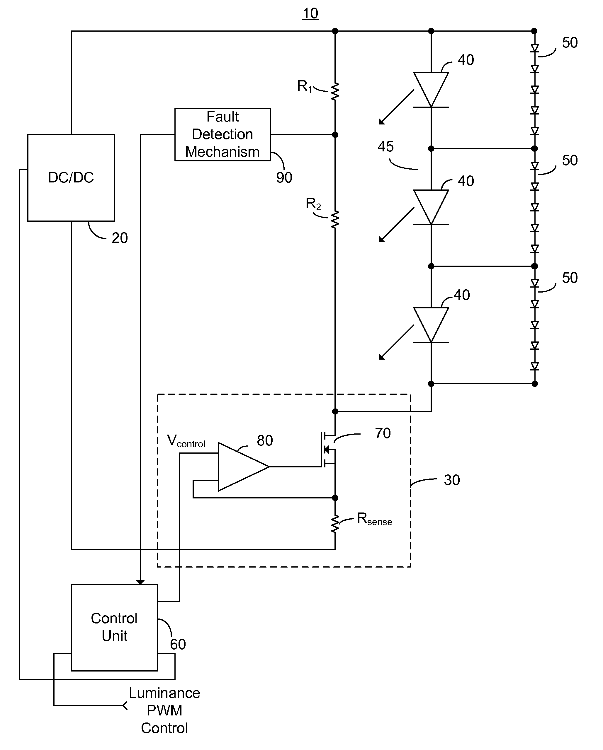
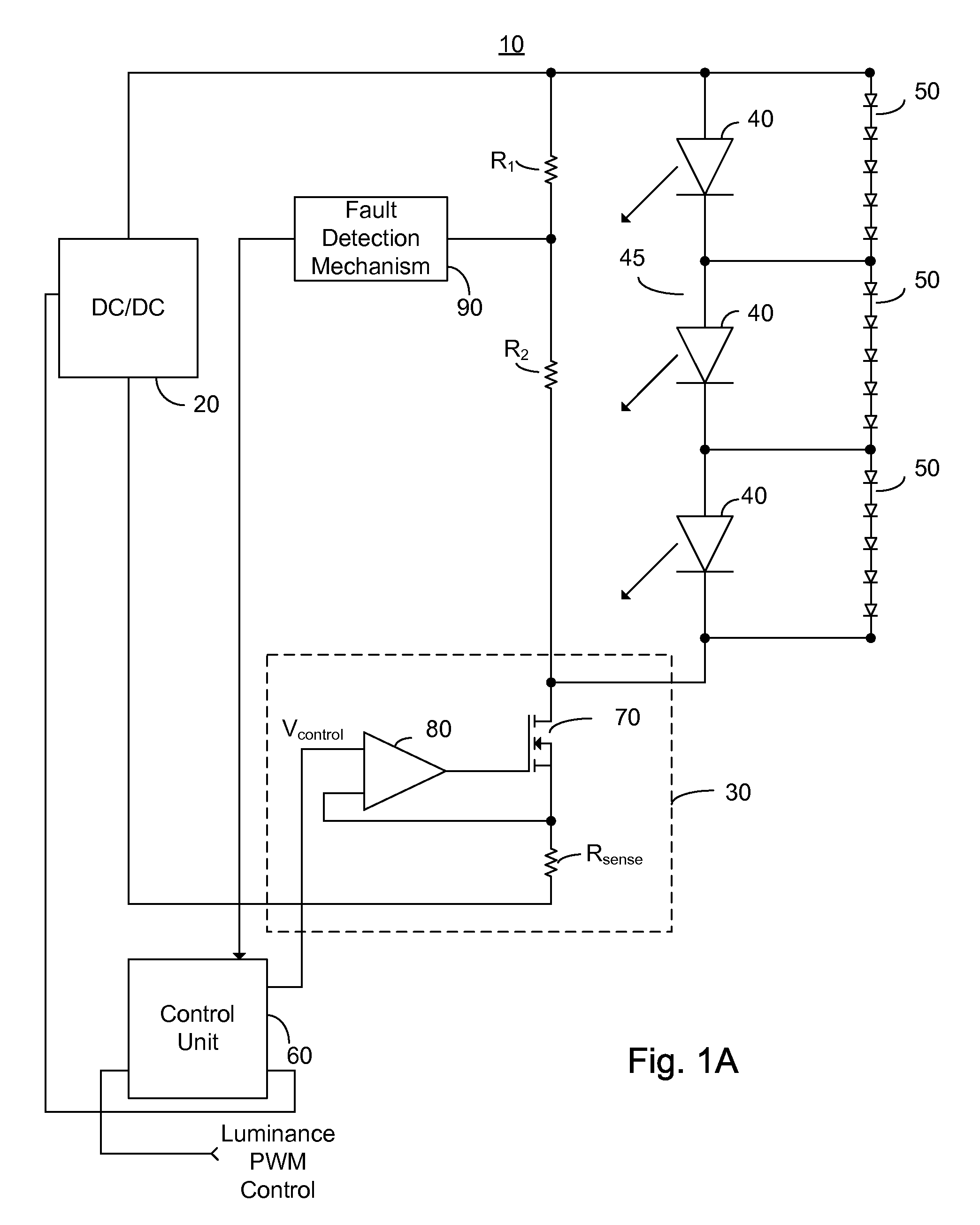
[0074]Embodiment 200 comprises a DC / DC converter 20; a constant current control 30; a fault detection and identification mechanism 210; a plurality of LEDs 40 connected serially to form an LED string 45; a plurality of protection diode strings 50; a control unit 220; and an LCD chromatic control unit 230. LCD chromatic control unit 230 comprises a memory 260. Constant current control 30 comprises a FET 70, a comparator and FET driver 80, and a sense resistor Rsense. Fault detection and identification mechanism 210 comprises a multiplexer 240 and a fault detection and control mechanism 250. FET 70 is illustrated as an N Channel MOSFET, however this is not meant to be limiting in any way, and FET 70 may be replaced with a P channel MOSFET, a bipolar transistor, or any other electronically controlled switch without exceeding the scope of the invention. FET 70 is advantageously shown as integrated within constant current control 30, which is preferably supplied as an ASIC, however this ...

embodiment 270

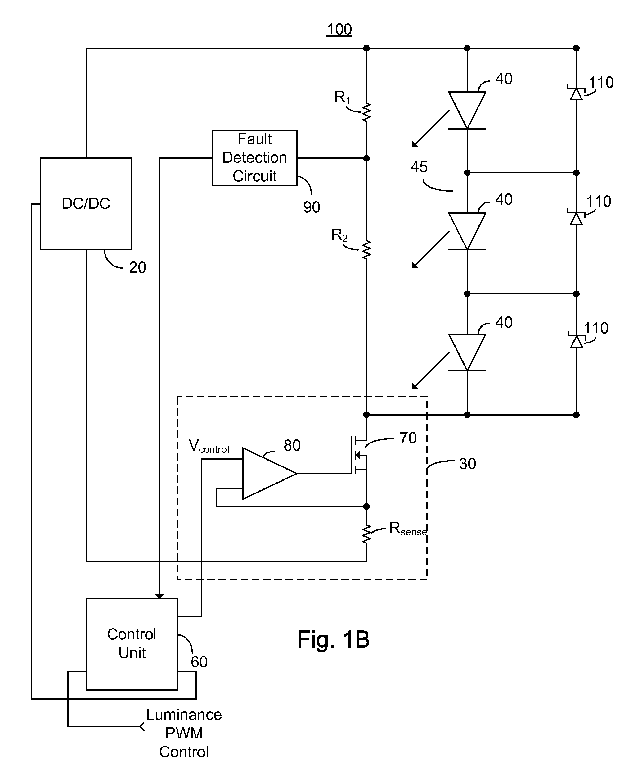
[0085]Embodiment 270 comprises a DC / DC converter 20; a constant current control 30; a fault detection and identification mechanism 210; a plurality of LEDs 40 connected serially to form an LED string 45; a plurality of Zener or breakdown diodes 110; a control unit 220; and an LCD chromatic control unit 230. LCD chromatic control unit 230 exhibits a memory 260. Constant current control 30 comprises a FET 70, a comparator and FET driver 80, and a sense resistor Rsense. Fault detection and identification mechanism 210 comprises a multiplexer 240 and a fault detection and control mechanism 250. FET 70 is illustrated as an N Channel MOSFET, however this is not meant to be limiting in any way, and FET 70 may be replaced with a P channel MOSFET, a bipolar transistor, or any other electronically controlled switch without exceeding the scope of the invention. FET 70 is advantageously shown as integrated within constant current control and fault identification unit 210, which is preferably su...

embodiment 280

[0096]Embodiment 280 comprises a DC / DC converter 20; a constant current control 30; a fault detection and identification mechanism 210; a plurality of LEDs 40 connected serially to form an LED string 45; a plurality of serially connected diodes 140 and voltage sources 150; a control unit 220; and an LCD chromatic control unit 230. LCD chromatic control unit 230 exhibits a memory 260. Constant current control 30 comprises a FET 70, a comparator and FET driver 80, and a sense resistor Rsense. Fault detection and identification mechanism 210 comprises a multiplexer 240 and a fault detection and control mechanism 250. FET 70 is illustrated as an N Channel MOSFET, however this is not meant to be limiting in any way, and FET 70 may be replaced with a P channel MOSFET, a bipolar transistor, or any other electronically controlled switch without exceeding the scope of the invention. FET 70 is advantageously shown as integrated within constant current control and fault identification unit 210...


PUM


Abstract

A fault detection mechanism for a LED string comprising a plurality of serially connected LEDs, the fault detection mechanism comprising: a control circuitry; and a voltage measuring means, in communication with the control circuitry, arranged to measure the voltage drop across at least one LED of the LED string, the control circuitry being operable to: measure the voltage drop, via the voltage measuring means, at a plurality of times, compare at least two of the measured voltage drops, and in the event the comparison of the at least two voltage drops is indicative of one of a short circuit LED and an open circuit LED, output a fault indicator.

Description

CROSS-REFERENCE TO RELATED APPLICATION[0001]This application claims priority from provisional patent application Ser. No. 60 / 756,991 filed Jan. 9, 2006, entitled “Self Healing Mechanism for LED Backlighting”, the entire contents of which is incorporated herein by reference.BACKGROUND OF THE INVENTION[0002]The present invention relates to the field of LED based lighting and more particularly to a fault detection mechanism for lighting based on a series LED string.[0003]Light emitting diodes (LEDs) and in particular high intensity LED strings are rapidly coming into wide use for lighting applications. High intensity LEDs are sometimes called high power LEDs, high brightness LEDs, high current LEDs or super luminescent LEDs and are useful in a number of lighting applications including backlighting for liquid crystal display (LCD) based monitors and televisions, collectively hereinafter referred to as a monitor. In a large LCD monitor typically the high intensity LEDs are supplied in a ...

Claims


Application Information

Patent Timeline
IPC IPC(8): H02H9/02
CPCH05B33/0869H05B37/03H05B33/089H05B33/0872H05B45/22H05B45/54
Inventor PEKER, ARKADIYKORCHARZ, DRORPINCU, DAVIDKAHN, SIMON
Owner POLARIS POWERLED TECH LLC
Why Eureka
Try Eureka