Methods and Systems Related to Pulsed Power

a technology of pulsed power and pulsed voltage, applied in the direction of overvoltage protection resistors, emergency protective arrangements for limiting excess voltage/current, and arrangements responsive to excess voltage, etc., can solve the problems of extraordinary demands on the devices used for power production, and is not possible. achieve the effect of high accuracy

Inactive Publication Date: 2007-07-12
CLARK COLLINS
View PDF10 Cites 17 Cited by
  • Summary
  • Abstract
  • Description
  • Claims
  • Application Information

AI Technical Summary

Benefits of technology

[0013] The present invention can provide for highly accurate pulse timing, which cans allow multiple pulsed power systems according to the present invention to be used together, in series or in parallel.

Problems solved by technology

Pulsed power applications such as these place extraordinary demands on the devices used for power production.
It is often desirable to combine the best features of each technique into an optimized solution for existing or new applications but this is not possible with the prior art.

Method used


Image

  • Methods and Systems Related to Pulsed Power
  • Methods and Systems Related to Pulsed Power
  • Methods and Systems Related to Pulsed Power

Examples


example embodiment

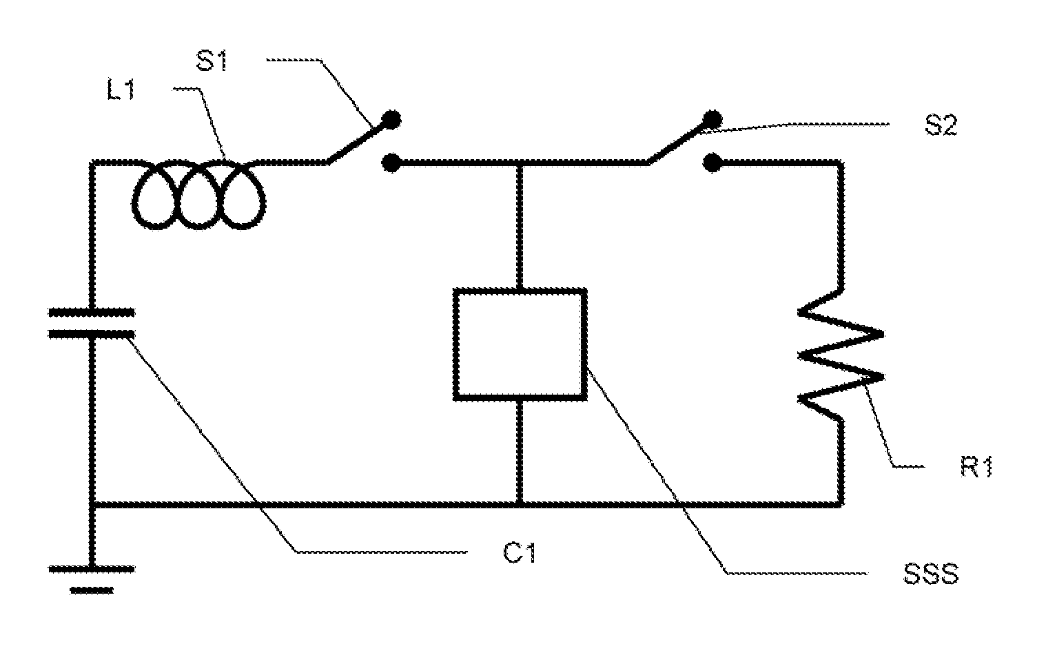
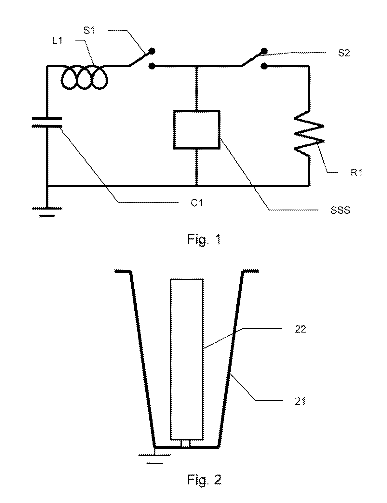
[0081] A specific implementation of the present invention is shown in FIG. 14. The various components are identified and are the physical embodiments of the components in the circuit diagram in FIG. 1. All components are mounted in a dielectric plate 20″×30″×2 thick and are assembled and installed with conventional pulsed power techniques and tools. Non-COTS components such as capacitor mounting hardware, inductor hardware, Marx switch hardware and output switch hardware are fabricated with conventional manufacturing techniques. This hardware is designed to drive a high power microwave load at 500 kilovolts, 10 kiloamperes, 200 nanoseconds. Those skilled in the art will appreciate several peripheral yet important components such as charge resistors, trigger components and high pressure containment vessel, not shown in the diagram but common to pulsed power systems.

[0082] The surge arrestor can also be made to provide step-wise voltage adjustment with an embodiment such as that illu...


PUM


Abstract

The present invention provides circuits and devices that allow improved performance from pulsed power systems. Some embodiments of the present invention comprise a MARX system; an inductor system in electrical communication with the MARX system; a surge arrestor system in electrical communication with the inductor system; an output switch system in electrical communication with the surge arrestor system; and a crowbar switch system in electrical communication with the output switch system. A static test load can be selectively coupled to the system for example at the output of the output switch or crowbar switch, to allow the system to be easily tested without risk to actual loads. An example static test load can include a plurality of metal oxide varistors connected in an electrical series and placed in electrical communication with the output terminal of the output switch and with the reference potential.

Description

CROSSREFERENCE TO RELATED APPLICATIONS [0001] This application claims the benefit of U.S. provisional application 60 / 775,292, “Pulsed Power System,” tiled Feb. 21, 2006, and claims priority as a continuation in part of U.S. patent application Ser. No. 11 / 433,032, “Methods and Apparatuses Related to Pulsed Power,” filed May 12, 2006, which application claims the benefit of U.S. provisional application 60 / 680,674, “Methods and Apparatuses Related to Pulsed Power,” filed May 13, 2005. Each of the applications listed above is incorporated herein by reference.BACKGROUND [0002] The present invention relates to methods and apparatuses related to pulsed power. More specifically, the present invention relates to circuits and devices suitable for use in shaping pulses in pulsed power systems, and pulsed power systems incorporating such circuits or devices. [0003] Pulsed power is used to generate and apply energetic beams and high-power energy pulses. It is distinguished by the development of ...

Claims


Application Information

Patent Timeline
Patent Type & Authority Applications(United States)
IPC IPC(8): H02H9/06
CPCH02H9/04H01T4/20H02H9/06H01T4/00
Inventor CLARK, COLLINS
Owner CLARK COLLINS
Why Eureka
Try Eureka