
Electronic blasting system

a technology of electronic blasting and blasting equipment, which is applied in the direction of make-and-break ignition, lighting and heating equipment, instruments, etc., can solve the problems of invariably using conventional hand-operated control equipment, causing errors, and causing errors in the operation of control equipment in this way

Inactive Publication Date: 2007-07-12
ORICA EXPLOSIVES TECH PTY LTD
View PDF14 Cites 11 Cited by
  • Summary
  • Abstract
  • Description
  • Claims
  • Application Information

AI Technical Summary

Benefits of technology

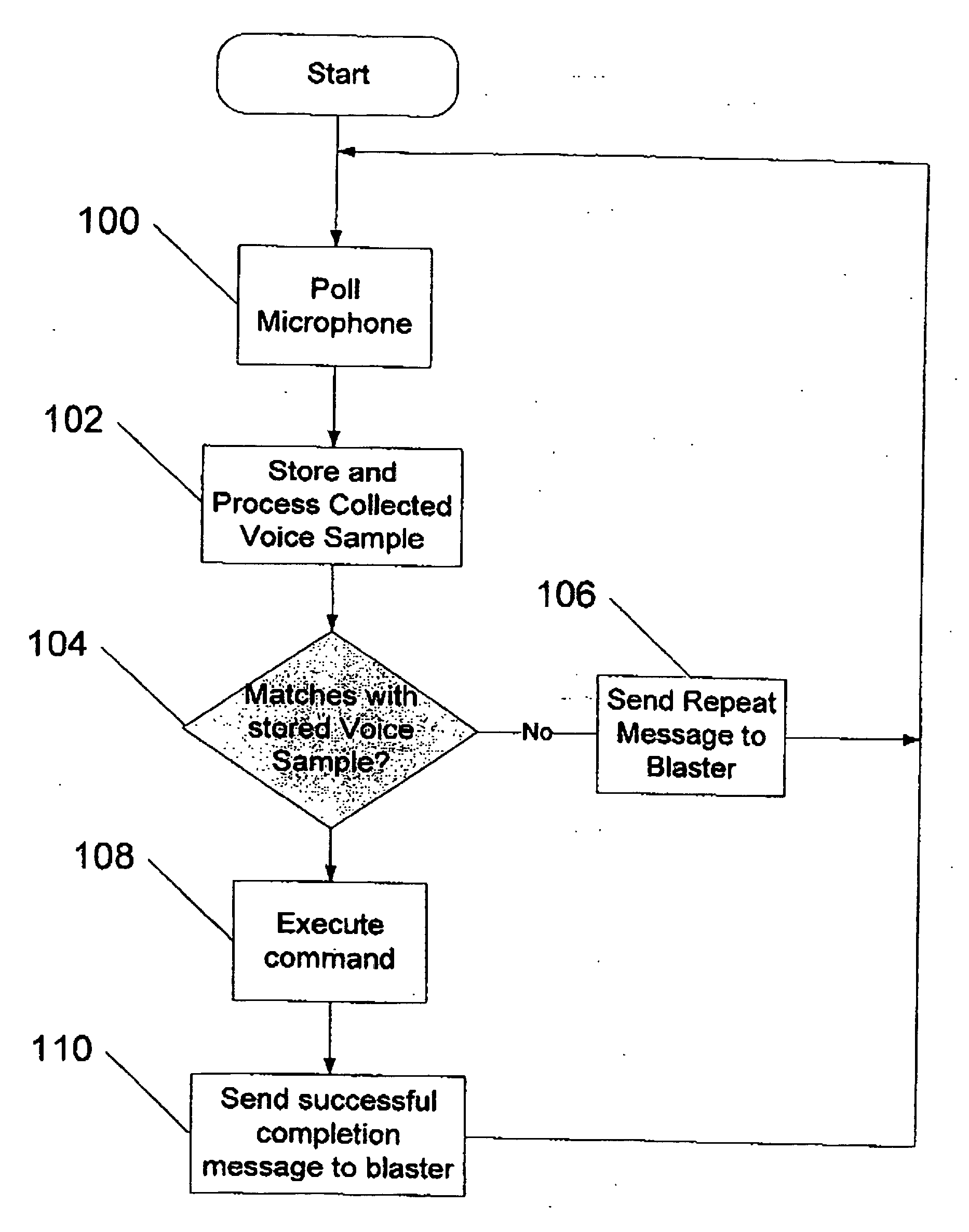
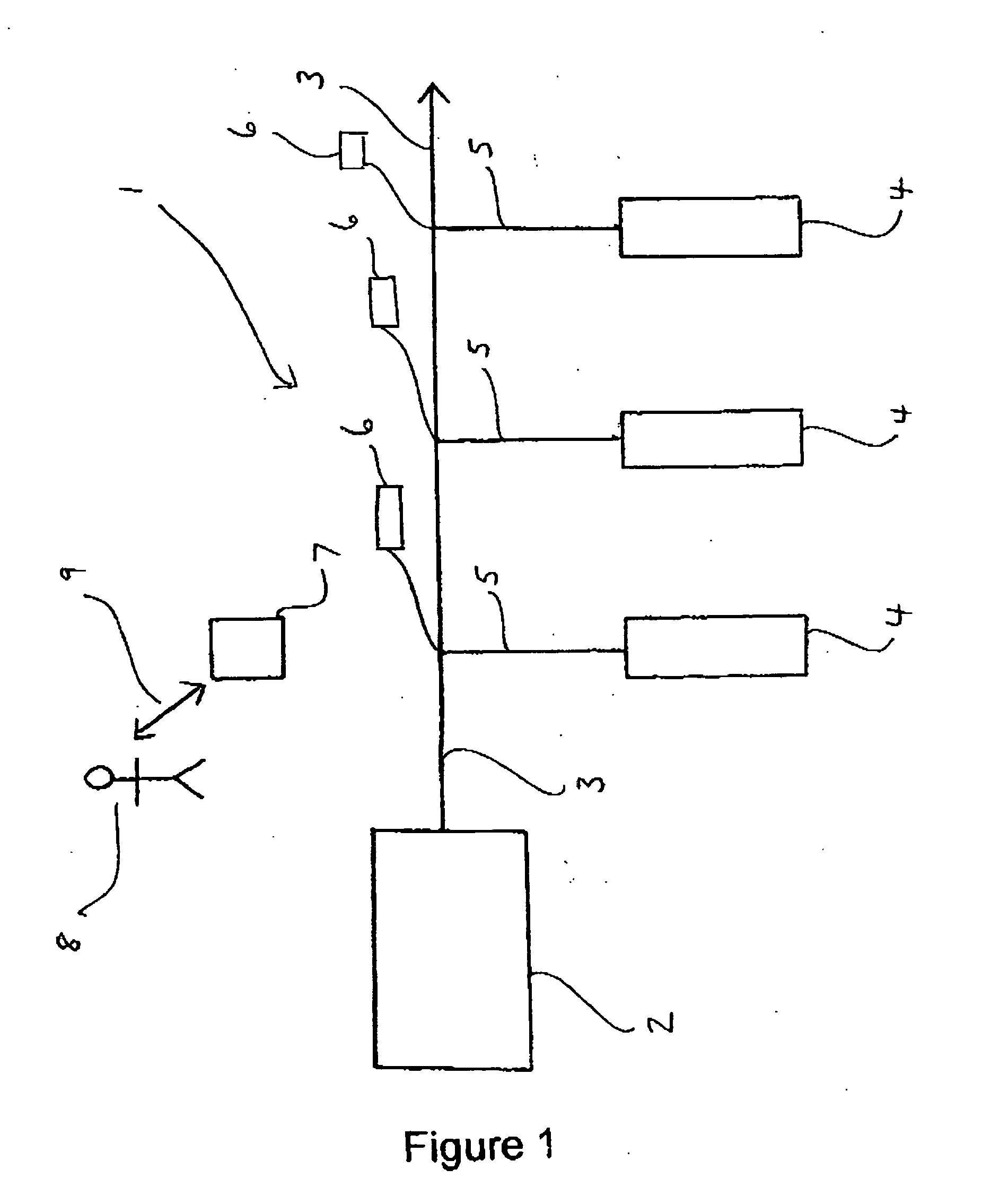
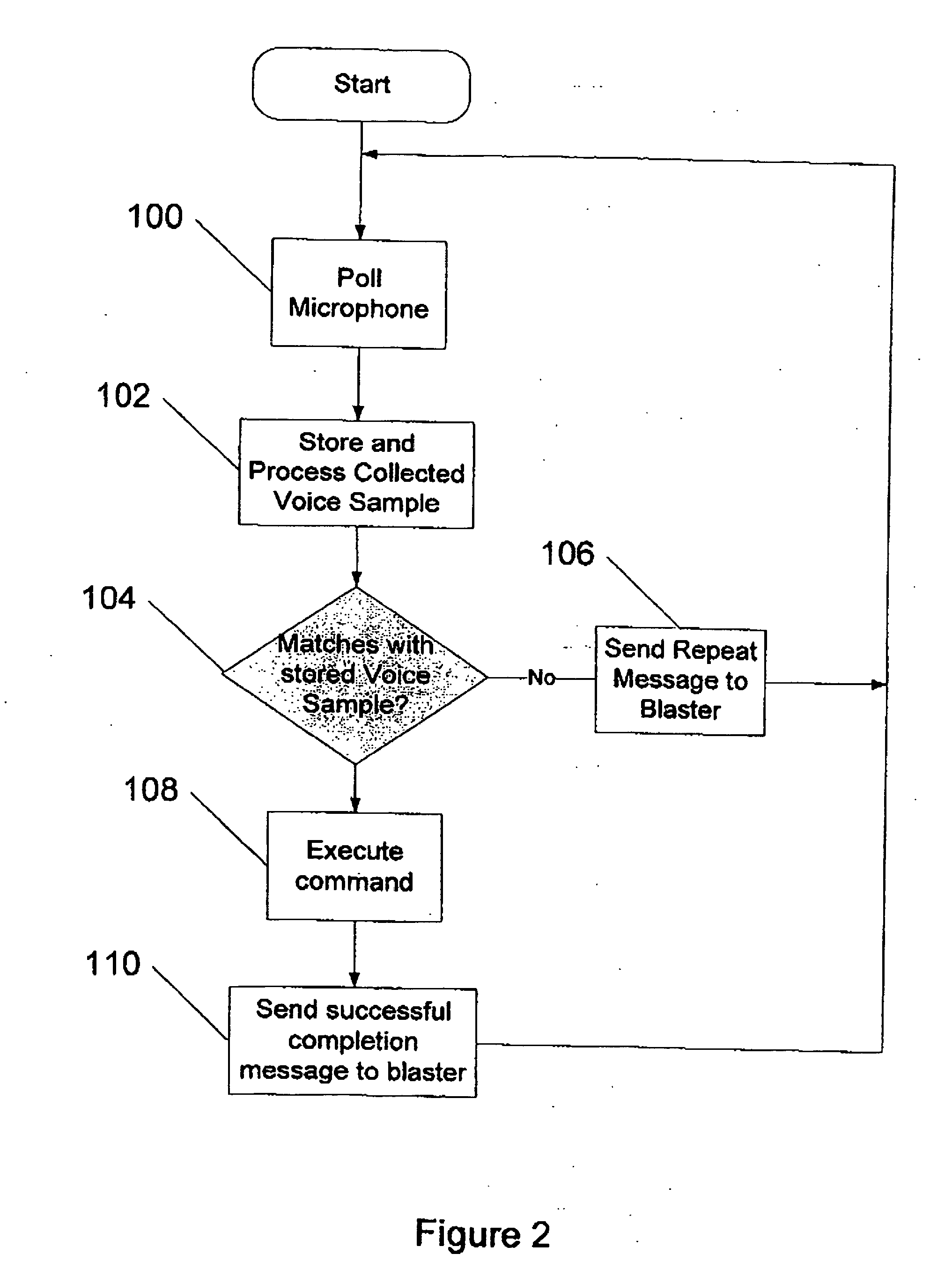
[0011] The present invention resides in the use of a blasting machine that may be operated by a blast operator under voice control in order to carry out some required action in the context of operating the electronic blasting system. Use of a blasting machine that is voice operable reduces the need for the blast operator to use his / her hands for operation of the device. As will be appreciated from the preceding discussion, this has significant practical advantages. The function of the blasting machine with respect to the one or more electronic detonators used in the blasting system may be conventional. However, the fact that this function is voice controlled in accordance with the invention is believed to represent a significant departure from the state of the art.

Problems solved by technology

Even when a skilled blast operator is involved, operation of control equipment in this way can be a source of errors.
This is especially so in the field when the control equipment is being operated under difficult conditions, such as when it is wet or humid and / or when ambient light levels are low.
Errors can also occur when a precise, and possibly complex, combination of keystrokes, or the like, is required to implement some equipment functionality.
Furthermore, use of conventional hand-operated control equipment invariably requires the blast operator to look at what he / she is doing to ensure that the correct buttons or keys are being pressed at the appropriate time.
In addition, the blast operator is inevitably distracted when reading (LCD) display screens which are characteristic of control equipment in common usage.
This can be especially problematic in dusty and / or wet conditions and / or when visibility is poor.
It should also be noted that LCDs tend to perform badly in cold conditions, such as might be encountered in locations such as Canada and the US.
All of these factors can mean that this kind of equipment is concentration / attention demanding to operate, and this can detract from other important roles the blast operator may have, such as observation and control of explosives loading.

Method used


Image

  • Electronic blasting system
  • Electronic blasting system
  • Electronic blasting system

Examples


Embodiment Construction

[0015] To enable the blasting machine to be operated under voice control the blast operator may speak into a microphone in communication with the blasting machine. This microphone may be provided on a headset or helmet to be worn by the blast operator. The microphone may be connected to the blasting machine by a wire. Alternatively, wireless technology may be used to relay voice input at the microphone to the blasting machine. In this case conventional wireless technology protocols and componentry may be used, such as Bluetooth™. Depending upon context the blast operator may be in close proximity to the blasting machine during operation of it. Alternatively, the blast operator may operate the blasting machine from a location remote from it. This may be required for safety reasons. In this case voice commands from the blast operator may be relayed to the blasting machine by a hard (wire) connection or using wireless technology.

[0016] When selecting a microphone, the signal-to-noise ...


PUM


Abstract

An electronic blasting system comprising: a plurality of electronic detonators; and a blasting machine, a function of which is to transmit information to and / or receive information about one or more of the plurality of electronic detonators, wherein the blasting machine is adapted to perform this function under voice control.

Description

BACKGROUND OF THE INVENTION [0001] The present invention relates to an electronic blasting system for use in blasting operations, for example in mining and quarrying. The present invention also relates to a method of blasting involving the electronic blasting system. The present invention further relates to components of the electronic blasting system. [0002] In general terms electronic blasting systems are well known in the art. A characteristic of such systems is the use of electronic delay detonators to achieve precise detonation, and preferably these detonators are fully programmable with respect to detonation delay time. The use of such detonators affords significant benefits in terms of blast control and design. [0003] A blasting system using electronic delay detonators involves a variety of control equipment in order to implement successfully a pre-determined blast design and to initiate a blast according to that design. Invariably, operation of the control equipment requires...

Claims


Application Information

Patent Timeline
IPC IPC(8): F23Q3/00F42D1/055F42D99/00
CPCF42D1/055F42D1/05
Inventor LOWNDS, CHARLES MICHAEL
Owner ORICA EXPLOSIVES TECH PTY LTD
Learn More