Electromagnetic wave generating device

a generator and electromagnetic wave technology, applied in the direction of electrical equipment, instruments, laser details, etc., can solve the problems of reducing both frequency band and efficiency, difficult to perform frequency sweep continuously in a wide band, and too narrow above-described frequency bands as tunable-spectral bands, etc., to achieve high output and high capability of substance identification

Inactive Publication Date: 2007-07-12
NISHIZAWA JUN ICHI +1
View PDF3 Cites 39 Cited by
  • Summary
  • Abstract
  • Description
  • Claims
  • Application Information

AI Technical Summary

Benefits of technology

[0007] An object of the present invention is to provide a frequency-tunable electromagnetic wave generator in a terahertz band, overcoming the above-d

Problems solved by technology

However, the above-described frequency band is too narrow as a tunable-spectral band for identifying a variety of living materials, by measuring differences in the terahertz electromagnetic wave spectroscopic spectra.
Therefore, the terahertz electromagnetic wave hv3, the pump beam hv3, and the beam hv3 overlap poorly which causes both frequency band and efficiency to decrease.
However, because of the mode hopp

Method used


Image

  • Electromagnetic wave generating device
  • Electromagnetic wave generating device
  • Electromagnetic wave generating device

Examples


first embodiment

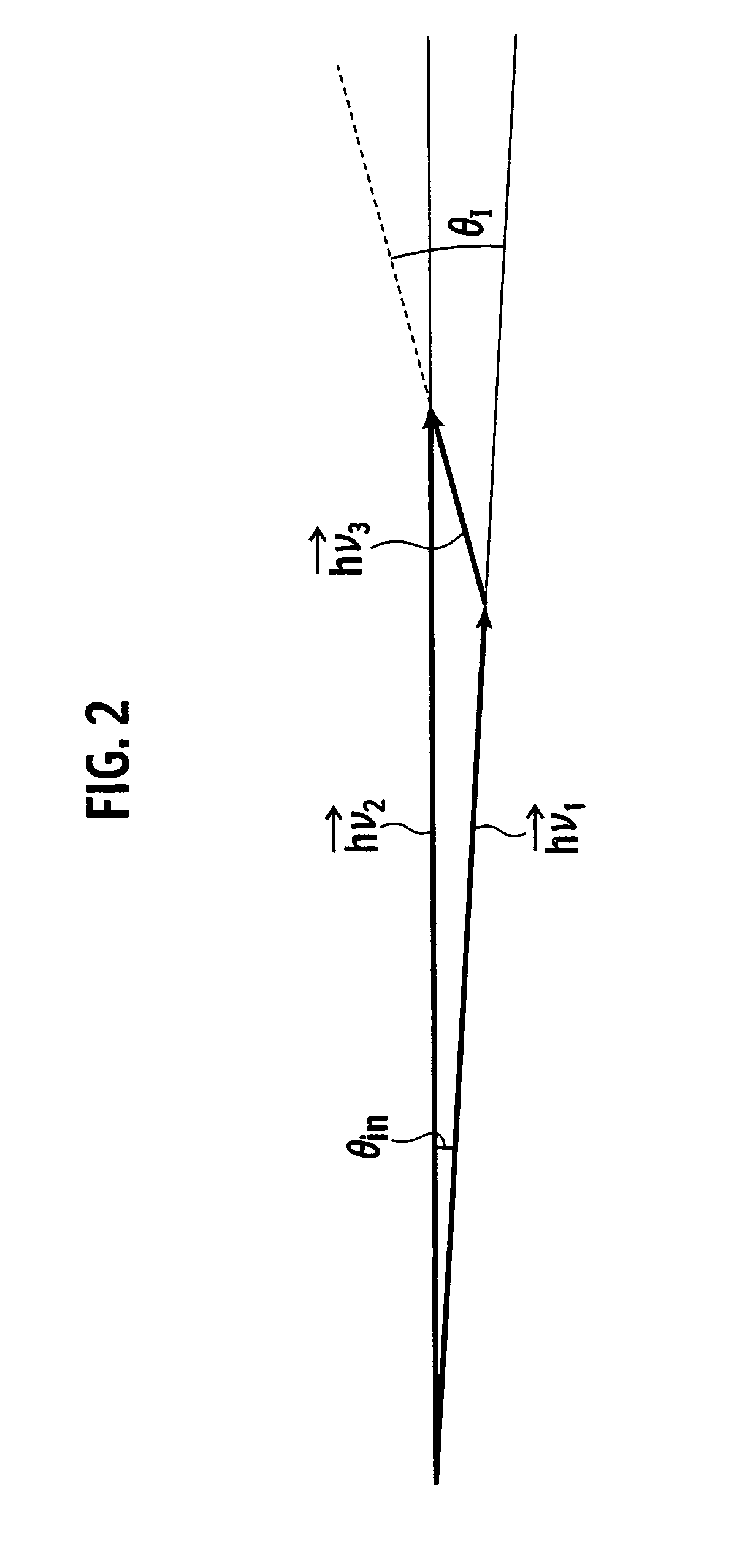
[0042] As shown in FIG. 4, an electromagnetic generator according to a first embodiment of the present invention encompasses a first pump beam emitter 2 configured to emit a first pump beam hv1 at wavelength longer than one micrometer, a second pump beam emitter 25 configured to emit a second pump beam hv2 at tunable-wavelength that is different from that of the first pump beam hv1, being longer than one micrometer, a nonlinear optical crystal 19 configured to generate an electromagnetic wave hv3 of difference-frequency between the first pump beam hv1 and the second pump beam hv2, and an optical system (M1, M2, 18) configured to irradiate the first pump beam and the second pump beam to the optical crystal 19, adjusting an external intersection angle Θinext to be less than 0.5° at difference-frequency v3=1 THz between the first pump beam hv1 and the second pump beam hv2. Here, the external intersection angle Θinext is an intersection angle between the first pump beam and the second p...

second embodiment

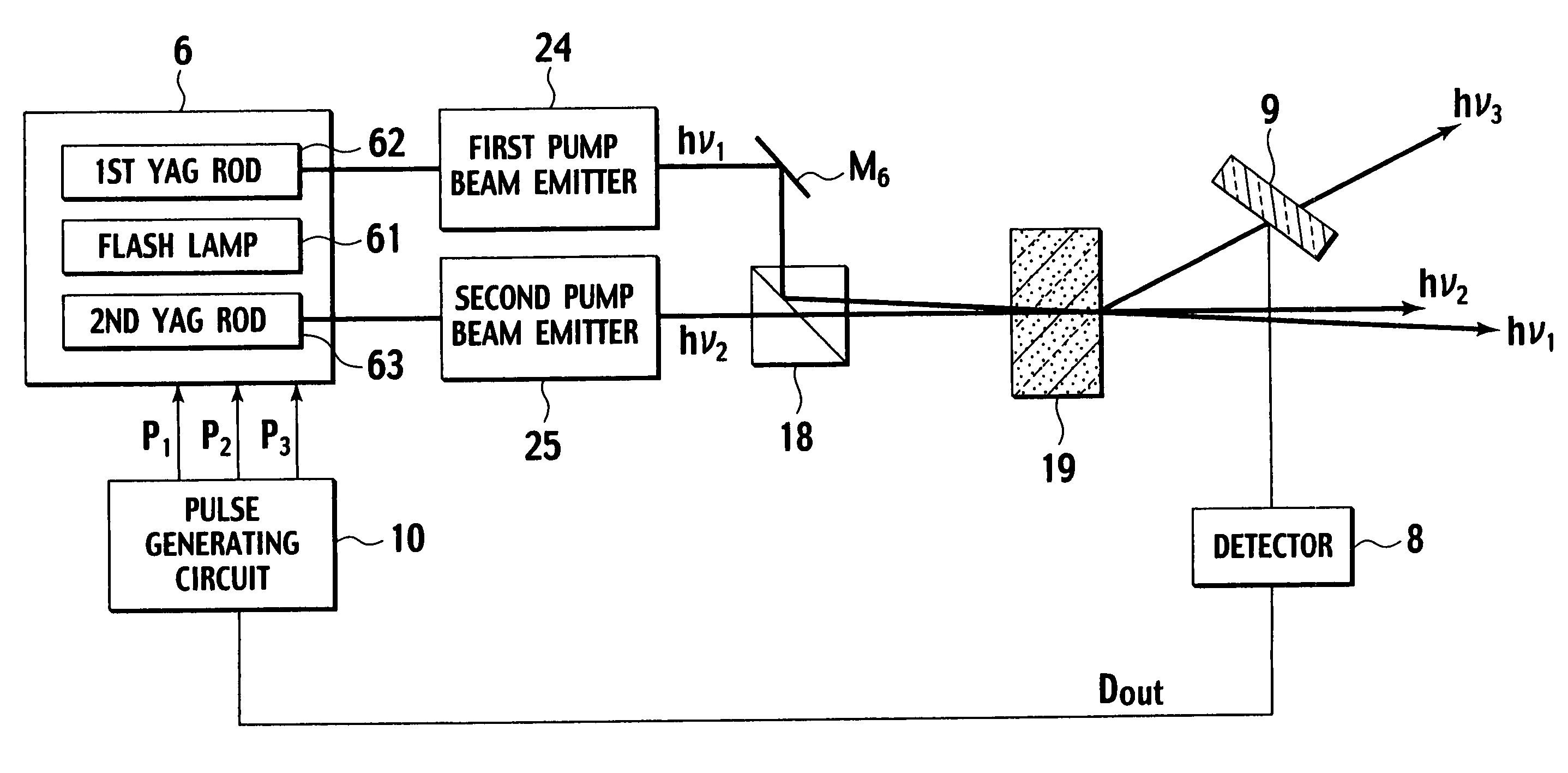
[0058] As shown in FIG. 6, an electromagnetic generator according to a second embodiment of the present invention encompasses a first pump beam emitter 24 configured to emit a first pump beam hv1 at wavelength longer than one micrometer, a second pump beam emitter 25 configured to emit a second pump beam hv2 at tunable-wavelength that is different from that of the first pump beam hv1, being longer than one micrometer, a nonlinear optical crystal 19 configured to generate an electromagnetic wave hv3 of difference-frequency between the first pump beam hv1 and the second pump beam hv2, and an optical system (M3, M4, M5, 18) configured to irradiate the first pump beam and the second pump beam to the optical crystal 19, adjusting an external intersection angle Θinext to be less than 0.5° at difference-frequency v3=1 THz between the first pump beam hv1 and the second pump beam hv2.

[0059] The optical system (M3, M4, M5, 18) embraces a half mirror M3, a first mirror M4, a second mirror M5 ...

third embodiment

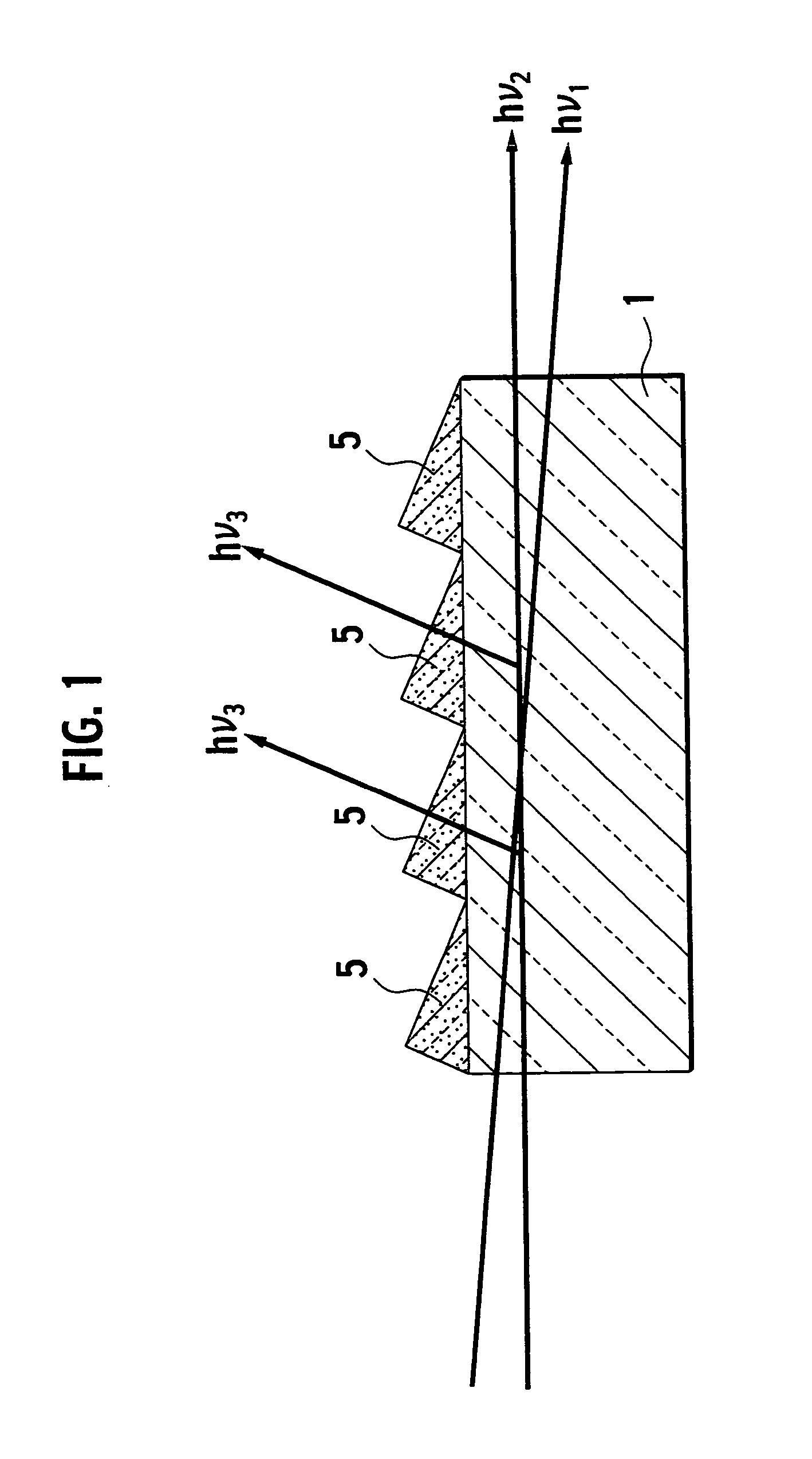
[0070] Although electromagnetic wave generator according to the third embodiment has almost same organization of the electromagnetic wave generators explained in the first and second embodiments, geometry of the nonlinear optical crystal 19 in the third embodiment is different from those of the first and second embodiments, because the nonlinear optical crystal 19 is formed into a triangular prism, which has a cross section of a right triangle as shown in FIG. 7. The terahertz electromagnetic wave hv3 will be emitted almost perpendicular to an electromagnetic wave exit face (outputting face) S3, if the pump beams hv1 and hv2 enter into an entrance face S1 defined by the hypotenuse (the longest side of the right triangle), by shaping the geometry of the nonlinear optical crystal 19 into the right triangle with an angle of approximately 30° and an angle of approximately 60° in a cross sectional view shown in FIG. 7.

[0071] For example, in a case when frequency v3 of the terahertz elec...


PUM


Abstract

An electromagnetic wave generator encompasses a first pump beam emitter (2) configured to emit a first pump beam (hv1) having a wavelength larger than one micrometer; a second pump beam emitter (25) configured to emit a wavelength-tunable second pump beam (hv2) having a wavelength larger than one micrometer, the wavelength of which is different from the wavelength of the first pump beam (hv1); a nonlinear optical crystal (19) configured to generate an electromagnetic wave (hv3) of a difference frequency between the first pump beam (hv1) and second pump beam (hv2); and an optical system (M1, M2, 18) configured to irradiate the first pump beam (hv1) and second pump beam (hv2) to the nonlinear optical crystal (19), by adjusting an external intersection angle between the first pump beam (hv1) and second pump beam (hv2) within 0.5° at the difference frequency of 1 THz. Here, a frequency-tunable terahertz electromagnetic wave (hv3) is generated in the nonlinear optical crystal (19), by changing the frequency of the second pump beam (hv2), being liked with the change of the external intersection angle.

Description

FIELD OF THE INVENTION [0001] The present invention relates to a frequency-tunable electromagnetic wave generator in terahertz band. BACKGROUND-ART [0002] A terahertz electromagnetic wave generator as shown in FIG. 1, which uses polariton mode in a Lithium Niobate (LiNbO3) crystal as a dielectric material, is known as a wavelength-tunable generator of a terahertz electromagnetic wave. In other words, in FIG. 1, a first pump beam (a first pump beam may simply be called “a pump beam”) hv1 and a second pump beam (a second pump beam may simply be called “a signal beam” or “an idler beam”) hv2 generate a terahertz electromagnetic wave by a difference-frequency generation hv3=hv1-hv2 with first and second pump beams entering a Lithium Niobate crystal. [0003] Thus, a coherent light of the terahertz electromagnetic wave hv3 in the frequency band of approximately from 0.7 THz to 2.5 THz is obtained. However, the above-described frequency band is too narrow as a tunable-spectral band for iden...

Claims


Application Information

Patent Timeline
IPC IPC(8): H01S3/10H01S3/093G02F1/35G02F1/37
CPCG02F2203/13G02F1/3534
Inventor NISHIZAWA, JUN-ICHISUTO, KENSASAKI, TETSUOTANABE, TADAOKIMURA, TOMOYUKI
Owner NISHIZAWA JUN ICHI
Why Eureka
Try Eureka