Optical transmitter and method for controlling optical transmitter
a technology of optical transmitters and optical transmitters, applied in electromagnetic transmission, electrical apparatus, transmission, etc., can solve the problems of significant deformation of ld conversion efficiency, difficult to increase extinct ratio, and increase in deterioration, so as to achieve optimal extinct ratio, detect ld deterioration, and rapid detection of ld deterioration
- Summary
- Abstract
- Description
- Claims
- Application Information
AI Technical Summary
Benefits of technology
Problems solved by technology
Method used
Image
Examples
first embodiment
[0047] It's explained by using FIGS. 1 to 3.
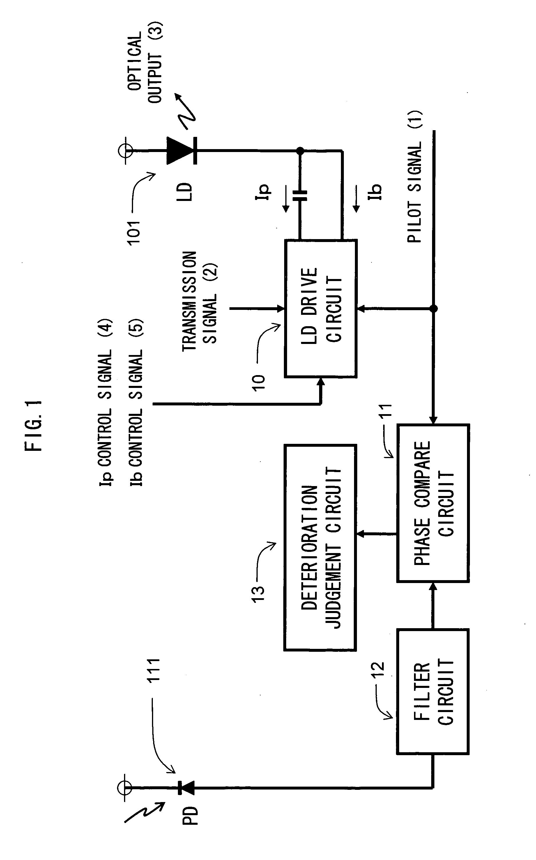
[0048]FIG. 1 is a diagram for explaining an example of the configuration of an optical transmitter according to an embodiment of the present invention. Reference numeral 101 denotes an LD, reference numeral 111 denotes a PD, reference numeral 10 denotes an LD drive circuit, reference numeral 11 denotes a phase compare circuit, reference numeral 12 denotes a filter circuit, and reference numeral 13 denotes a deterioration judgement circuit.
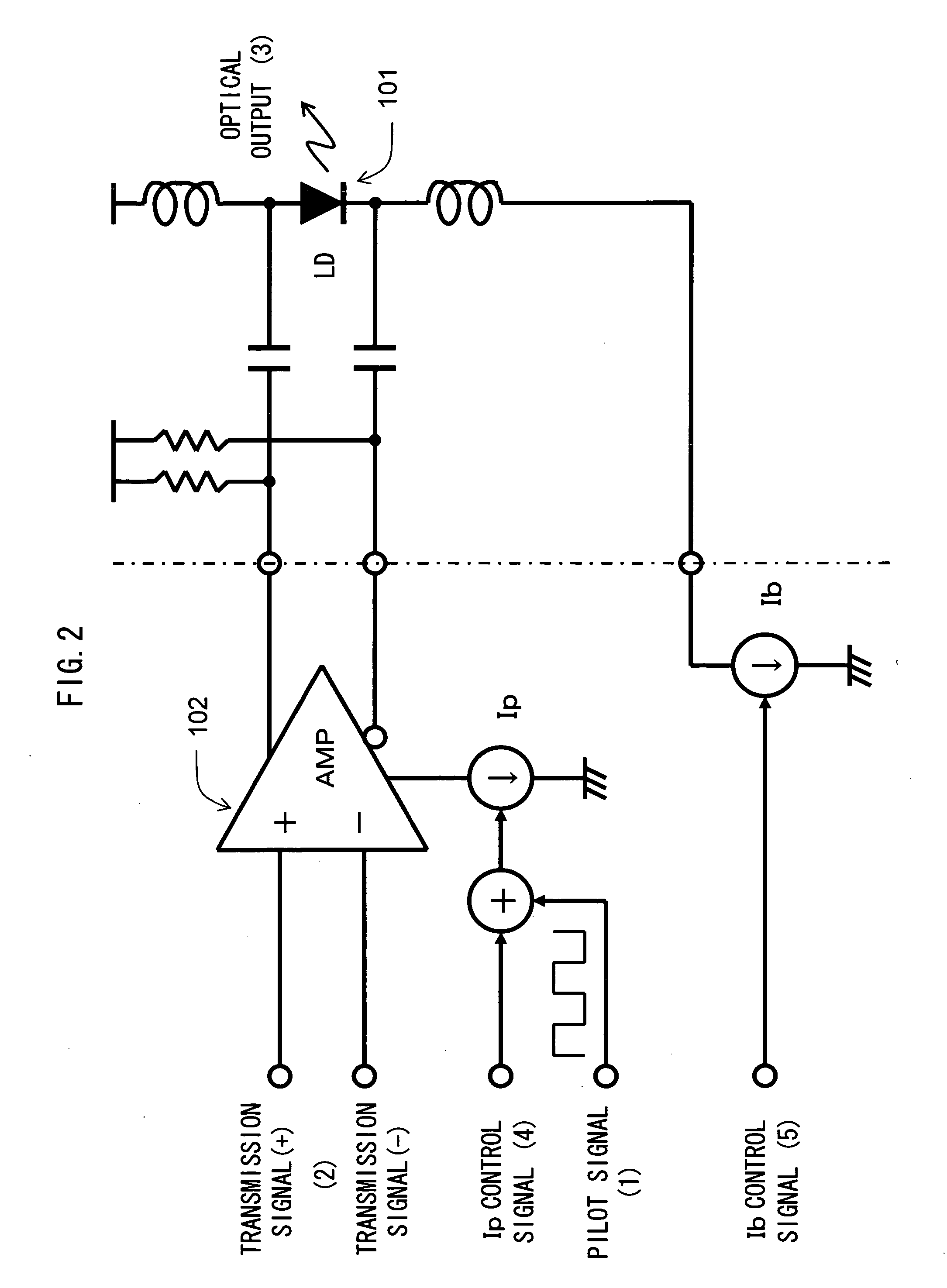
[0049]FIG. 2 is a diagram for explaining direct modulation of the LD 101 according to this embodiment. Compared with the configuration shown in FIG. 12, a pilot signal (1) is superimposed on a modulation current Ip. By superimposing the generated pilot signal (1) on an Ip control signal (4), a transmission signal (2) is modulated in accordance with the modulation current Ip on which the pilot signal (1) is superimposed, and is applied to the LD 101 biased in accordance with a bias current Ib controlled ...
second embodiment
[0060]FIG. 4 is a diagram for explaining an example of the operation of the optical transmitter according to another embodiment of the present invention. Compared with the operation described with reference to FIG. 3, an operation of the optical transmitter when deterioration occurs in an LD conversion efficiency curve will be explained.
[0061] For an optical output (13) obtained by converting the LD current (6), a pilot signal of a positive phase on the side of logical level “1” is completely suppressed, in accordance with an LD conversion efficiency curve (18) when the LD 101 deteriorates. Similarly, for a PD current (17) that monitors the optical output (13), a pilot signal of a positive phase on the side of logical level “1” is completely suppressed.
[0062] Thus, the filter circuit 12 extracts only a pilot signal of a negative phase on the side of logical level “0”.
[0063] The phase compare circuit 11 compares the phase of the pilot signal of the negative phase on the side of lo...
third embodiment
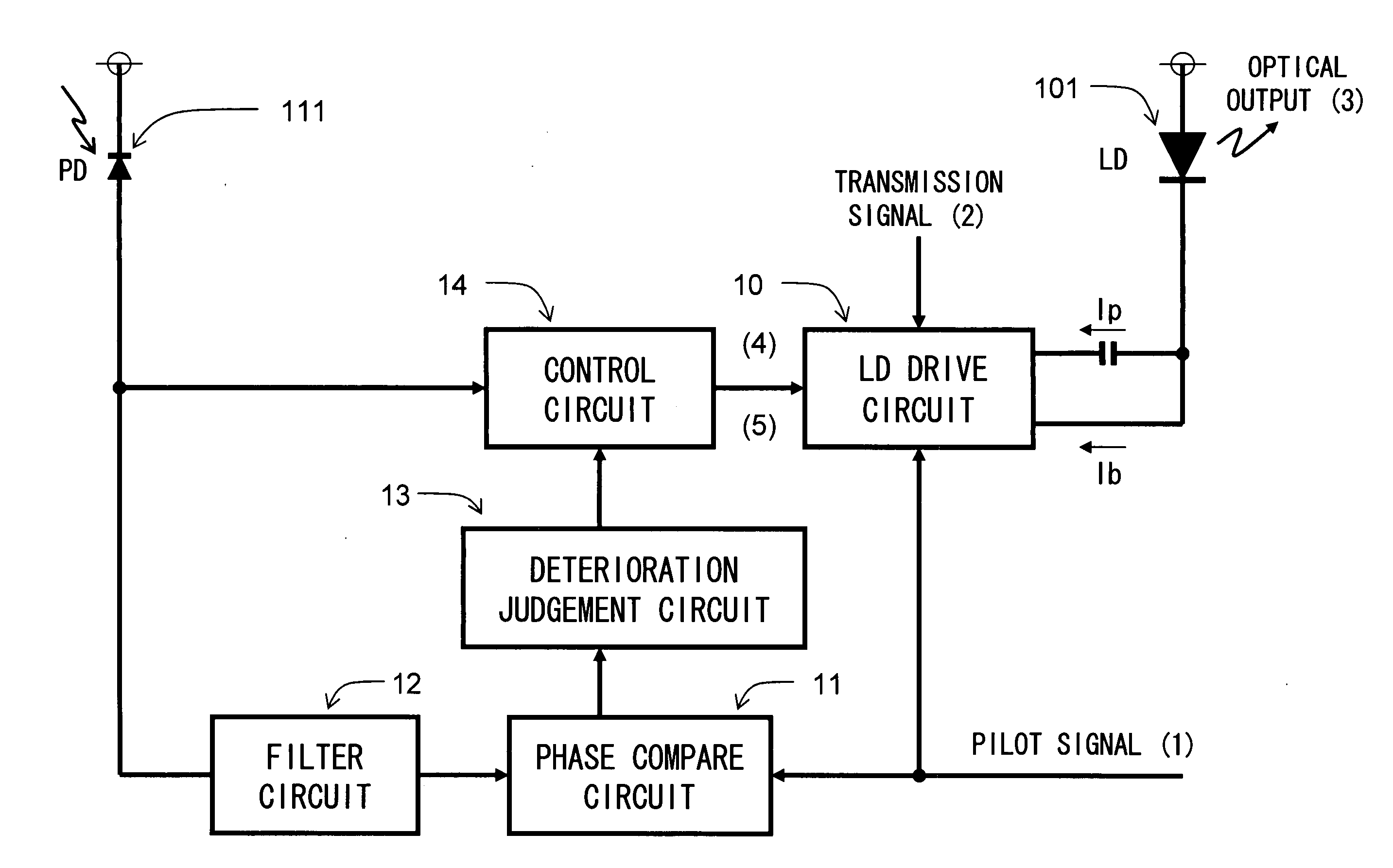
[0065]FIG. 5 is a diagram for explaining an example of the configuration of the optical transmitter according to another embodiment of the present invention. Compared with the configuration shown in FIG. 1, a control circuit 14 controls the LD drive circuit 10 in accordance with a deterioration judgement result of the deterioration judgement circuit 13 and a monitor signal of the PD 111.
[0066]FIG. 6 is a diagram for explaining an example of the operation of the optical transmitter according to this embodiment. Compared with the operation described with reference to FIG. 3, although the same LD conversion efficiency curve (8) is acquired, the bias current Ib is smaller. Thus, the operation point and the motion range of the LD 101 are lower, and part of the motion range of the LD 101 is less than the LD threshold current Ith.
[0067] In the operation point and the motion range of the LD 101, for an optical output (23) obtained by converting the LD current (6), a pilot signal of a nega...
PUM
 Abstract
Description
Claims
Application Information
 - R&D
- Intellectual Property
- Life Sciences
- Materials
- Tech Scout
- Unparalleled Data Quality
- Higher Quality Content
- 60% Fewer Hallucinations
Browse by: Latest US Patents, China's latest patents, Technical Efficacy Thesaurus, Application Domain, Technology Topic, Popular Technical Reports.
© 2025 PatSnap. All rights reserved.Legal|Privacy policy|Modern Slavery Act Transparency Statement|Sitemap|About US| Contact US: help@patsnap.com


