Separator for fuel cell, method for producing separator, and solid oxide fuel cell

Inactive Publication Date: 2007-07-12
MITSUBISHI MATERIALS CORP +1
View PDF6 Cites 9 Cited by
  • Summary
  • Abstract
  • Description
  • Claims
  • Application Information

AI Technical Summary

Benefits of technology

[0021] According to the second aspect of the present invention, all the surfaces exposed to the fuel gas, which include not only the surface of the separator but also the wall surface of the inner flow passage and the like, are plated with silver, copper, or one of silver and copper alloys, as a result of which carburizing resistance of the separator can be remarkably improved, and deterioration of the separator caused by carburization can be suppressed even when methane gas and the like is used as the fuel gas.
[0022] Further, one or both surfaces of the plate-shaped member are arranged to be plated with silver,

Problems solved by technology

This results in a problem that electrode reaction may not be uniform on the cell face to cause deviation of current density distribution within the cell face and thereby the efficiency of the power generation cell (output power density per unit area) may be remarkably decreased.
Further, the electrode reaction as exothermic reaction which is not uniformly performed within the cell face, causes a temperature gradient to be formed in the power generation cell, as a result of which the power gen

Method used


Image

  • Separator for fuel cell, method for producing separator, and solid oxide fuel cell
  • Separator for fuel cell, method for producing separator, and solid oxide fuel cell
  • Separator for fuel cell, method for producing separator, and solid oxide fuel cell

Examples


first embodiment

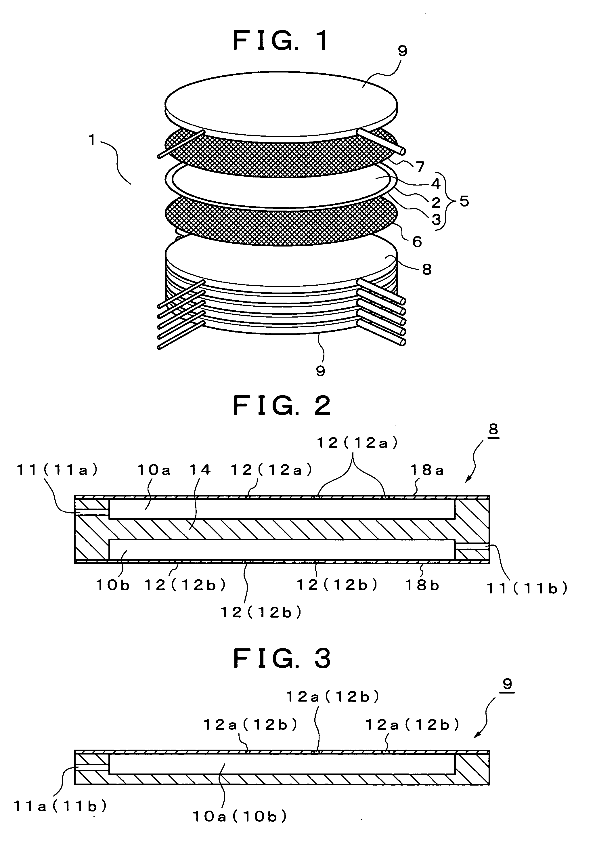
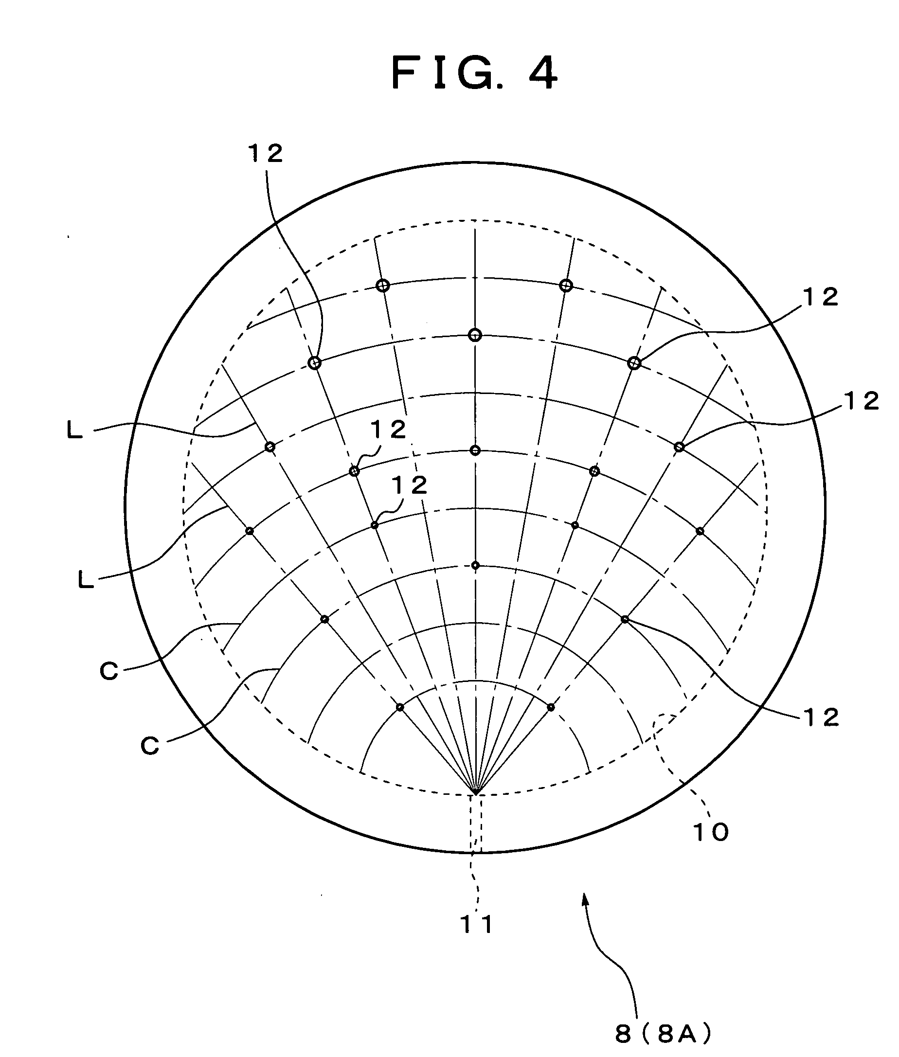
[0037]FIG. 1 shows a first embodiment of a solid oxide fuel cell according to the present invention, and reference numeral 1 in FIG. 1 denotes a fuel cell stack. As shown in FIG. 1, the fuel cell stack has a constitution formed by laminating in order a power generation cell 5 in which a fuel electrode layer 3 and an air electrode layer 4 are arranged on both surfaces of a solid electrolyte layer 2, a fuel electrode current collector 6 on the outer side of the fuel electrode layer 3, an air electrode current collector 7 on the outer side of the air electrode layer 4, separators 8, (the uppermost and lowermost layer of which are formed as end plates 9), on the outer side of each of the current collectors 6, 7. In the fuel cell stack 1, a seal-less structure in which a gas leakage prevention seal is not particularly provided in the outer peripheral part of the power generation cell 5 is adopted.

[0038] Here, the solid electrolyte layer 2 is formed of stabilized zirconia (YSZ) doped wit...

second embodiment

[0051]FIG. 11 shows a second embodiment of the solid oxide fuel cell according to the present invention, in which the same components as those in the above described first embodiment are denoted by the same reference numerals and the explanation thereof is simplified.

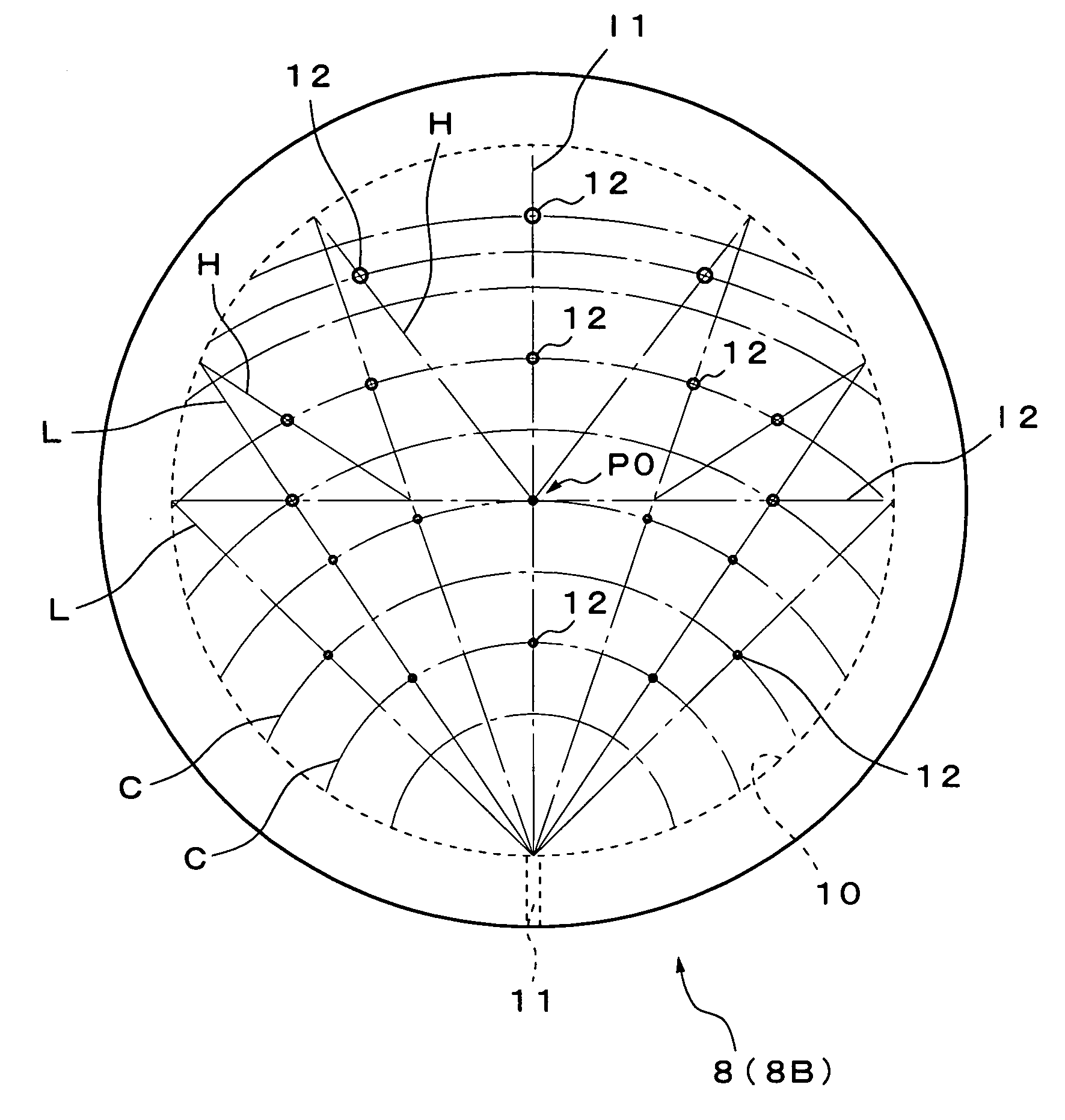
[0052] The fuel cell stack 1 according to the present embodiment has a seal-less structure similar to the above described first embodiment, and has a constitution formed by laminating in order a power generation cell 5 in which a fuel electrode layer 3 and an air electrode layer 4 are arranged on both faces of a solid electrolyte layer 2, a fuel electrode current collector 6 on the outer side of the fuel electrode layer 3, an air electrode current collector 7 on the outer side of the air electrode layer 4, and separators 8 (the uppermost and lowermost layers of which are formed as end plates 9) on the outer side of each of the current collectors 6, 7.

[0053] The separator 8 has a function to electrically connect the po...


PUM

PropertyMeasurementUnit
Diameteraaaaaaaaaa
Areaaaaaaaaaaa
Durabilityaaaaaaaaaa

Abstract

Gas discharge ports are provided in almost the entire area of a layer surface of a separator, and a gas for reaction is discharged like a shower from the separator toward a power generation cell. The separator is constructed by layering plate-shaped members containing iron-base alloy, nickel-base alloy, or chrome-base alloy as the base material. Silver, silver alloy, copper, or copper alloy is plated on both sides or one side of the base material of the plate-shaped member. The construction above can increase durability of a separator and enables the separator and a solid oxide fuel cell to be stably used for a long period.

Description

TECHNICAL FIELD [0001] The present invention relates to a separator for fuel cell, a method for producing the separator, and a solid oxide fuel cell (SOFC). BACKGROUND ART [0002] As is well known, the solid oxide fuel cell has been investigated and developed as one of various kinds of fuel cells for power generation. As the structure of the solid oxide fuel cell, there are proposed at present three types of structures: a cylindrical type, a monolithic type, and a flat plate laminated type. However, the flat plate laminated type structure is widely adopted for low-temperature operating type solid oxide fuel cell. [0003] In the flat plate laminated type solid oxide fuel cell, a fuel cell stack is constituted by alternately laminating power generation cells and separators in a state where a current collector is sandwiched between the power generation cell and the separator. The power generation cell has a laminated structure in which a solid electrolyte layer made of an oxide ion condu...

Claims


Application Information

Patent Timeline
IPC IPC(8): H01M8/02H01M8/12B05D5/12B32B37/00
CPCH01M8/0206H01M8/021H01M8/0228Y02E60/525H01M8/0258H01M2008/1293Y02E60/50H01M8/025H01M8/0263H01M8/241H01M8/2457H01M8/2483
Inventor YAMADA, TAKASHIYAMADA, MASAHARUAKBAY, TANERHOSHINO, KOJIMIYAZAWA, TAKASHIKOTANI, TAKAFUMIKOMADA, NORIKAZU
Owner MITSUBISHI MATERIALS CORP
Why Eureka
Try Eureka