

Embedded system insuring security and integrity, and method of increasing security thereof
- Summary
- Abstract
- Description
- Claims
- Application Information
AI Technical Summary
Benefits of technology
Problems solved by technology
Method used
Image

Examples
first embodiment
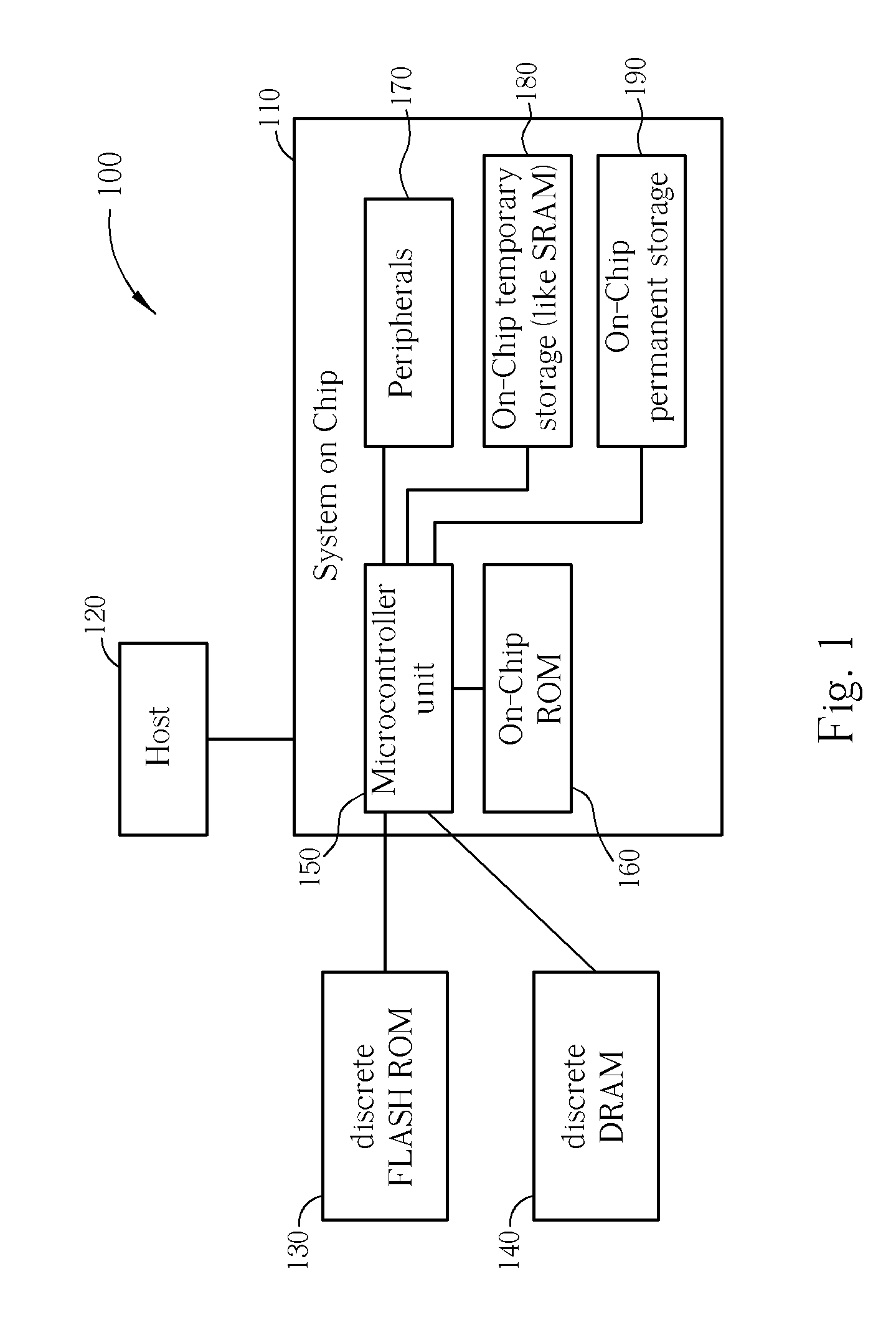
[0027] Please refer to FIG. 1, which is a block diagram of an embedded system 100 according to the present invention. The embedded system 100 includes a System on Chip Application-Specific Integrated Circuit (ASIC) 110, a discrete FLASH ROM module 130, and a discrete DRAM module 140. The ASIC 110 includes a microcontroller unit (MCU) 150, an on-chip ROM 160, which may be a form of Flash Memory, on-chip peripheral units 170, an on-chip temporary storage 180, and an on-chip permanent storage 190. If the embedded system 100 is a data storage device, there would usually be a host 120 like a PC or MPEG side in consumer electronics (CE) player environment.
[0028] The microcontroller unit 150 is coupled via on-chip communication channels to the on-chip ROM 160, the on-chip peripheral units 170, the on-chip temporary storage 180, and the on-chip permanent storage 190, and is coupled via off-chip communication channels to the off-chip FLASH ROM module 130, and the off-chip discrete DRAM modul...
second embodiment
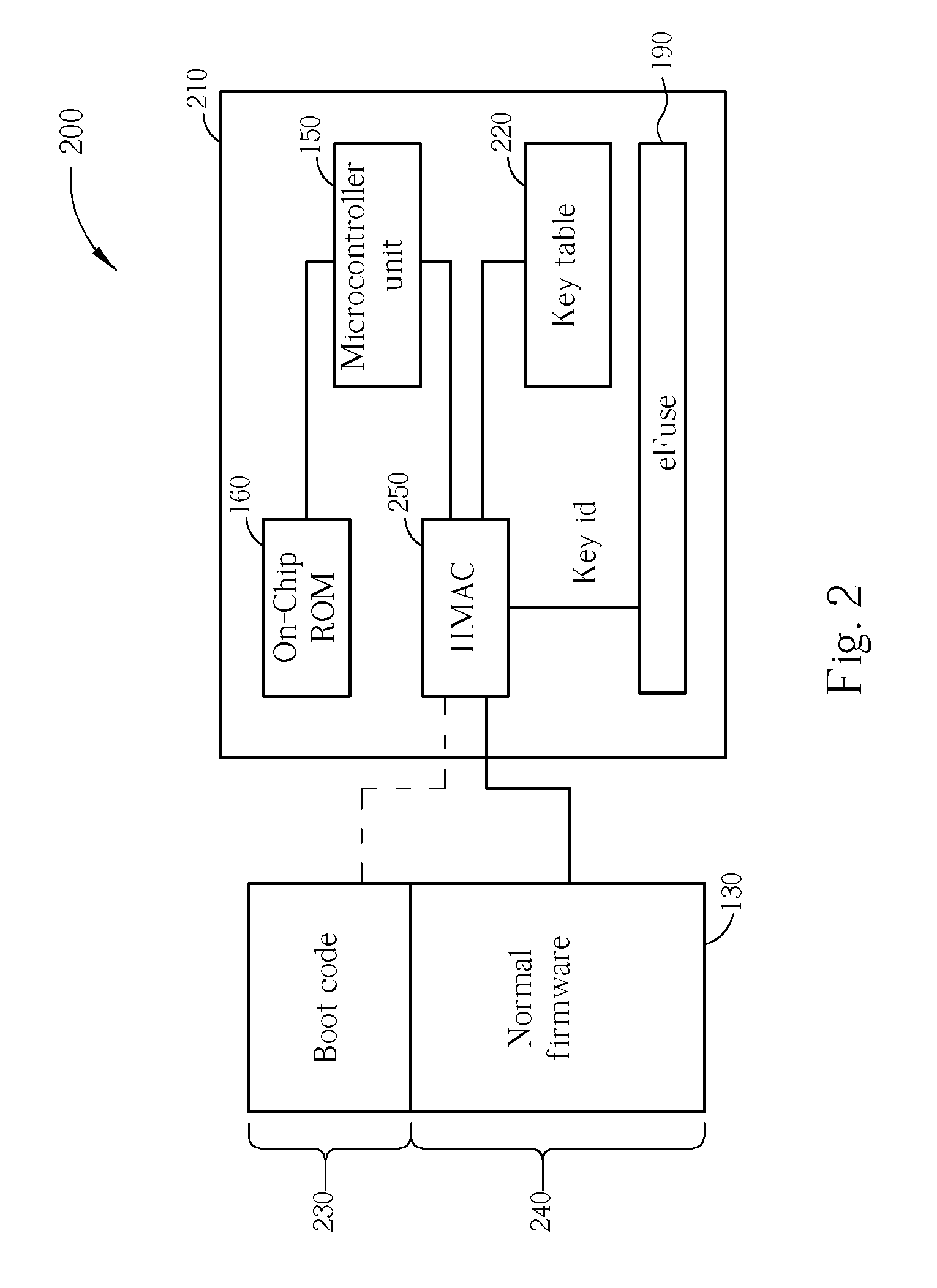
[0032] Please refer to FIG. 2, which is a functional block diagram of an embedded system 200 according to the invention. The embedded system 200 includes all of the same components as the embedded system 100 even if omitted from FIG. 2 to focus attention on a boot operation for the embedded system 200. As shown in FIG. 2, an ASIC 210 includes a Hash-based Message Authentication Code (HMAC) module 250 and optionally a key table 220 according to design considerations.
[0033] The chip vendor embeds a block of on-chip ROM 160 to be executed before the embedded system 200 fetches any boot code 230 from the external discrete FLASH ROM 130 during the corresponding boot operation. The firmware stored in the on-chip ROM 160 loads the key data from the eFuse 190 into the HMAC module 250, and the HMAC module 250 checks the integrity of external codes or firmware. If the key data stored in the eFuse 190 is the entire secret key, the HMAC module 250 can use the retrieved secret key directly to va...
third embodiment
[0035] Please refer to FIG. 3, which is a functional block diagram of an embedded system 300 as used during a normal firmware update, according to the invention. The embedded system 300 includes all of the same components as the embedded system 100 even if omitted from FIG. 3 to focus attention on a normal firmware update operation for the embedded system 300. As shown in FIG. 3, an ASIC 310 includes the Hash-based Message Authentication Code (HMAC) module 250 and optionally the key table 220 according to design considerations.
[0036] During a normal firmware update, the embedded system 300 is controlled by execution of firmware from a normal memory device 140, such as DRAM, which receives the firmware update from a host preferably via a normal advanced technology attachment packet interface (ATAPI) command. The embedded system 300 first checks integrity of a new firmware image corresponding to the firmware update, and then stores the updated firmware into the FLASH ROM 130. The HMAC...
PUM
 Abstract
Description
Claims
Application Information