Liquid cooling system with thermoeletric cooling module

Inactive Publication Date: 2007-07-19
COOLER MASTER CO LTD
View PDF6 Cites 27 Cited by
  • Summary
  • Abstract
  • Description
  • Claims
  • Application Information

AI Technical Summary

Benefits of technology

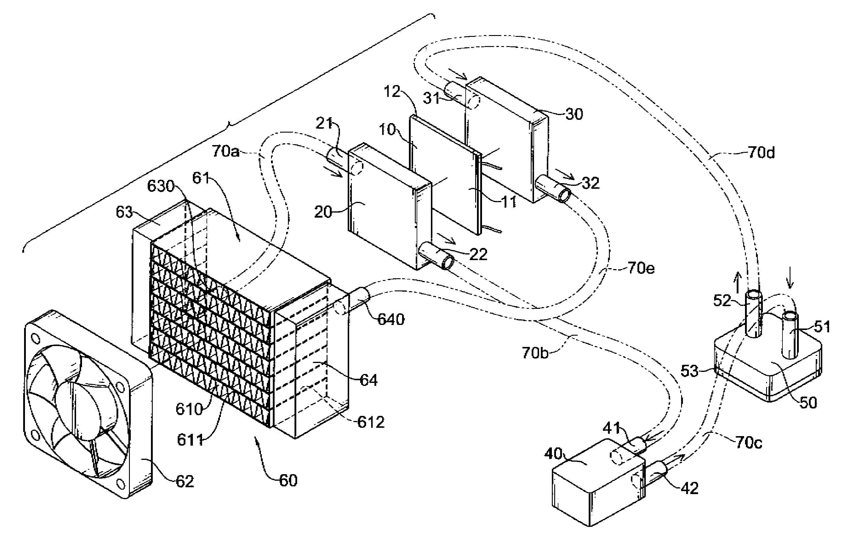
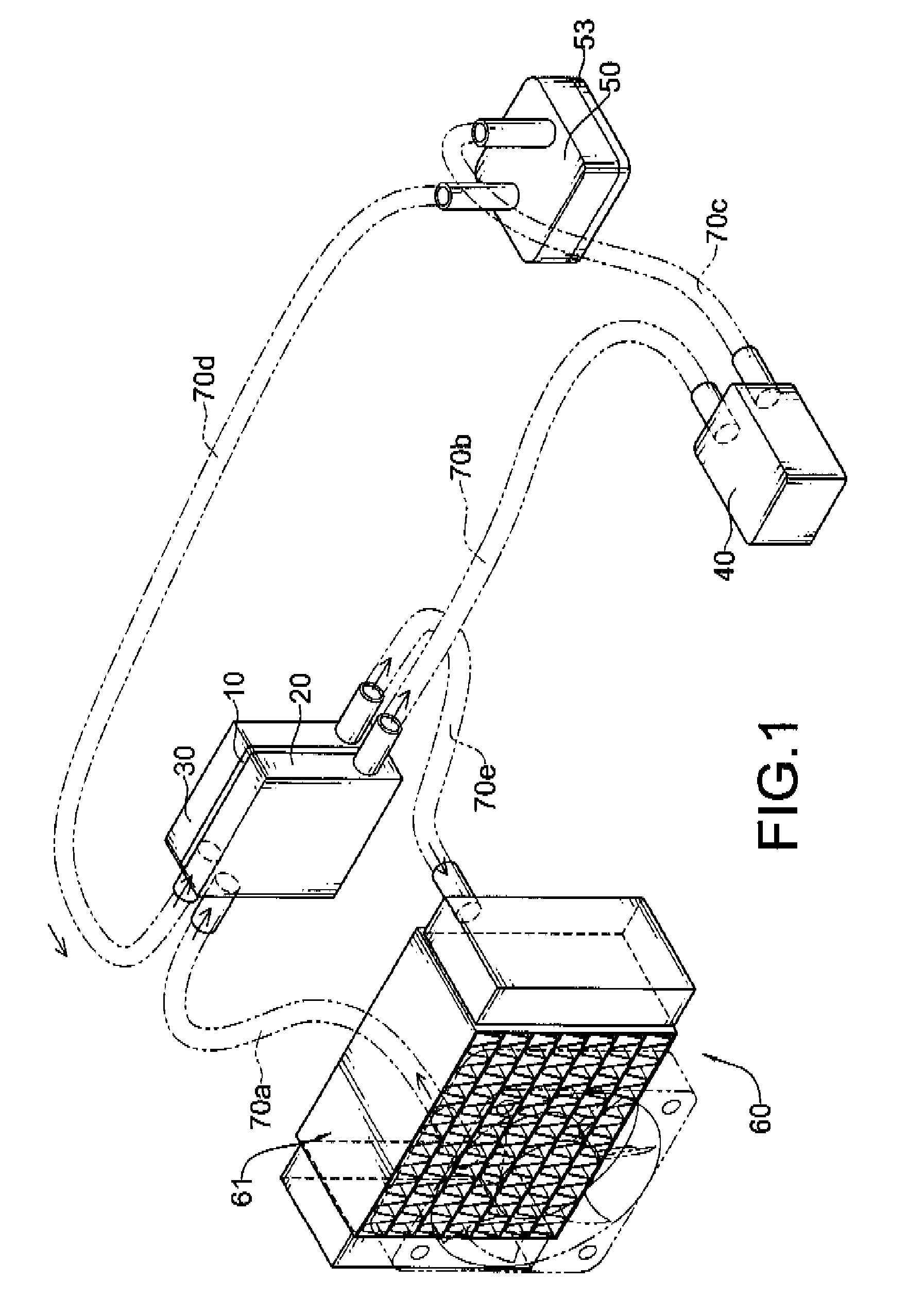
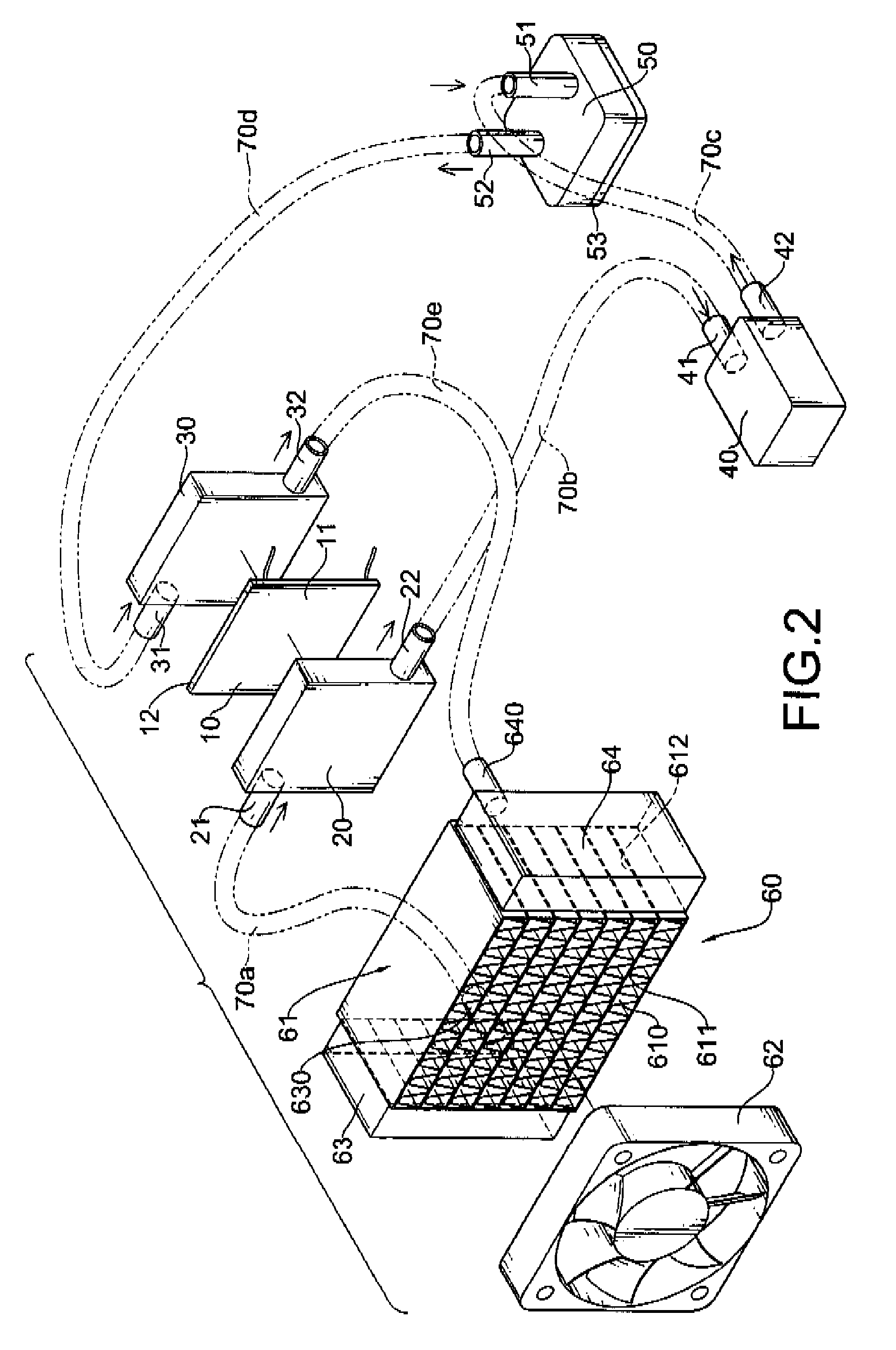
[0014]With such an arrangement, heat generated by the processor is quickly absorbed by the liquid. Then, the liquid takes heat away from the processor to the heat dissipating assembly for dissipation. Additionally, when the liquid pass through the hot surface, the liquid absorbs the heat of the hot surface transferred from the cold surface so as to reduce the temperature of the hot surface and to prevent the thermoelectric cooling module from burning.
[0015]With activity of the therm

Problems solved by technology

Since computer hardware is developed rapidly and provides high performance, as a result, there is a significant problem of computer processor overheating.
Current solutions based on passive fan or fin assembly are only just able to cope with the heat generated by the conventional computer and may unable to dissipate extraordinary heat generated by t

Method used


Image

  • Liquid cooling system with thermoeletric cooling module
  • Liquid cooling system with thermoeletric cooling module
  • Liquid cooling system with thermoeletric cooling module

Examples


Example

[0034]With further reference to FIG. 3, in the second embodiment, the fourth and fifth guide tubes (70d)(70e) and the hot plate (30) are replaced by the sixth guide tube (70f). The sixth guide tube (70f) is flexible, may be made of rubber or metallic and connects the joint head (52) of the water block (50) to the tube (640) of the heat dissipating assembly (60). Such that recycling of the liquid is faster and average temperature of the liquid may be lower.

Example

[0035]With further reference to FIG. 4, in the third embodiment, the pressure increasing device (40) and the water block (50) aforementioned are integrated into a pressure increasing cooling device (80). The pressure increasing cooling device (80) pressurizes liquid flow and has two tubes (81,82) and a contacting surface (53) attached to a processor of a computer. Such that the second guide tube (70b) connects the joint pipe (22) of the cold plate (20) to the tube (81). The sixth guide tube (70f) connects the tube (82) to the tube (640) of the heat dissipating assembly (60). With such an arrangement, the liquid cooling system in accordance with the present invention is more compact.

Example

[0036]With further reference to FIG. 5, in the fourth embodiment, the second guide tube (70b) connects the joint pipe (22) of the cold plate (20) to the tube (81) of the pressure increasing cooling device (80). The seventh guide tube (70g) connects the tube (82) to the joint pipe (21) of the cold plate (20). With such an arrangement, the liquid cooling system in accordance with the present invention is much more compact.

[0037]Otherwise, aforementioned pressure increasing cooling device (80) may be replace by said water block (50), such the second guide tube (70b) connects the joint pipe (22) of the cold plate (20) to the joint head (51) of the water block (50). The seventh guide tube (70g) connects the joint head (52) to the joint pipe (21) of the cold plate (20).

[0038]wherein one of the joint heads of the water block connects with one side the cold plate via a guide tube and the other joint head of the water block connects with the other side of the cold plate via a guide tube.


PUM


Abstract

A liquid cooling system has a thermoelectric cooling module, a heat dissipating assembly, a water block and multiple flexible guide tubes with liquid flows inside. The thermoelectric cooling module has a cold surface and a hot surface. The water block has a contacting surface attached to a processor of a computer. The guide tubes are mounted between the thermoelectric cooling module, the heat dissipating assembly and the water block. With the thermoelectric cooling module, the liquid cooling system can cool a processor of computer hardware with high efficiency, and is able to dissipate extraordinary heat generated by the processor.

Description

BACKGROUND OF THE INVENTION[0001]1. Field of the Invention[0002]The present invention relates to a cooling system, and more particularly to a liquid cooling system with thermoelectric cooling module that can cool a processor of a computer more efficiently, and dissipate much more of extraordinary heat generated by the processor[0003]2. Description of Related Art[0004]Since computer hardware is developed rapidly and provides high performance, as a result, there is a significant problem of computer processor overheating.[0005]The most common solution for cooling a working computer processor is to use a heat dissipating fan or a heat dissipating fin assembly to take away heat generated by the computer processor. Mostly, the heat dissipating fan or heat dissipating fin assembly is mounted securely in a case of the computer hardware and has air or water as coolant to flow through and to absorb heat.[0006]However, as the function of the computer hardware becomes more efficient, more heat ...

Claims


Application Information

Patent Timeline
IPC IPC(8): F25B21/02
CPCF25B21/02H01L23/473H01L2924/0002H01L2924/00
Inventor CHIEN, YI-SHENHSU, I-TA
Owner COOLER MASTER CO LTD
Why Eureka
Try Eureka