Hollow fiber membrane module

Inactive Publication Date: 2007-07-19
TORAY IND INC
5 Cites 54 Cited by

AI-Extracted Technical Summary

Problems solved by technology

However, troublesome and time-consuming work is necessary to close the ends of a large number of hollow fiber membranes.
In addition, it is seen that the flow rate of raw water in the cylindrical case tends not to be uniform and, if not uniform actually, particular portions of the hollow fiber membranes tend to move more heavily than necessary and hit other hollow fiber membranes, resulting in damage to hollow fiber membranes.
During air scrubbing, furthermore, the flow of air tends not to be uniform and, if not uniform actually, the hollow fiber membranes tend not to be swung uniformly for particulate matter removal, or hollow fiber membranes, which can swing freely, ma...

Method used

[0072]The plugging member (small bundle forming member) used in the hollow fiber membrane module of the invention is preferably made of resin in view of the role to bundle a plurality of hollow fiber membranes and plug their ends. Preferred resins include thermosetting ones such as epoxy resin, urethane resin, epoxy acrylate resin, silicone resin and polyester resin, and a variety of thermoplastic one such as polyethylene, polypropylene, and the material used in the hollow fiber membranes. Resin to be used preferably has a type A durometer hardness of about 5 to 95 according to JIS-K6253 (2004) in order to prevent damage to the hollow fiber membranes in areas where the plugging members (small bundle forming members) contact with the hollow fiber membranes. It is also preferred that a layer of resin with the hardness is provided over another resin layer with a higher hardness. The durometer hardness according to JIS-K6253 (2004) is measured with a measuring instrument as described in JIS-K6253 (2004) by pressing the stylus against the surface of the resin. If it is impossible to perform the pressing operation, a sample may be prepared to be used for the measurement.
[0080]To prevent a decrease in a packing density of the hollow fiber membranes in the cylindrical case caused by existence of the plugging members (small bundle forming members), it is preferred that each plugging member (small bundle forming member) is shifted relative to its neighbor in the direction of the axis of the module (vertical direction).
[0081]Part of each plugging member (small bundle forming member) may be connected to neighboring plugging member (small bundle forming member). Such connection may be achieved with a rod or a string. This connection, which serves to join all plugging members (small bundle forming members), prevent only those plugging members (small bundle forming members) located in a certain area from swinging, and works to propagate the vibration and swinging motions all other plugging members (small bundle forming members). At the same time, the position of each small bundle can be controlled moderately. This enhances the dispersion of raw water and air. An enhanced dispersion serves to facilitate the prevention of contamination on hollow fiber membranes and prevention of entanglement of small bundles.
[0089]The hanging string 2b is formed by, for example, a thread or rod. As the thread, there is, for example, a metal wire, a natural or synthetic resin fiber, or a metal or resin tube, and as the rod, there is, for example, a metal rod, a natural or synthetic resin rod, or a metal or resin tube. As the resin, there is, for example, polyethylene resin, polypropylene resin, polyvinyl chloride resin, or acrylic resin. As the metal, there is, for example, stainless...

Benefits of technology

[0034]According to the hollow fiber membrane module of the invention, a large number of hollow fiber membranes are divided into several small bundles at one end, which is generally the bottom end during use, and their ends, put together in each bundle, are closed, which allows each small bundle of hollow fiber membranes to swing moderately during the filtration and air scrubbing processes, facilitating the prevention of particulate matter accumulation and efficient removal of the particulate matter.
[0035]It is also possible to use a relatively large flow path for water discharge from the back washing process, allowing the water discharge to be completed in a short period of time. In addition, the end plugging member (small bundle forming member) in each small bundle acts as a weight, serving to maintain the position of each small bundle at a roughly fixed point if raw water and air flow between there. This prevents the hollow fiber membranes from swinging more heavily than necessary to cause damage to each other or get tangled. Furthermore, the ends of the hollow fiber membranes that are at the bottom during...

Abstract

A hollow fiber membrane module comprising a large number of hollow fiber membranes contained in a cylindrical case, wherein one end of each hollow fiber membrane, which is left open, is fixed to the cylindrical case, while the other ends of the hollow fiber membranes are divided into more than one small bundles, with the ends, contained in separate small bundles, being kept together and plugged.

Application Domain

Technology Topic

Mechanical engineeringHollow fiber membrane

Image

  • Hollow fiber membrane module
  • Hollow fiber membrane module
  • Hollow fiber membrane module

Examples

  • Experimental program(8)

Example

EXAMPLE 1
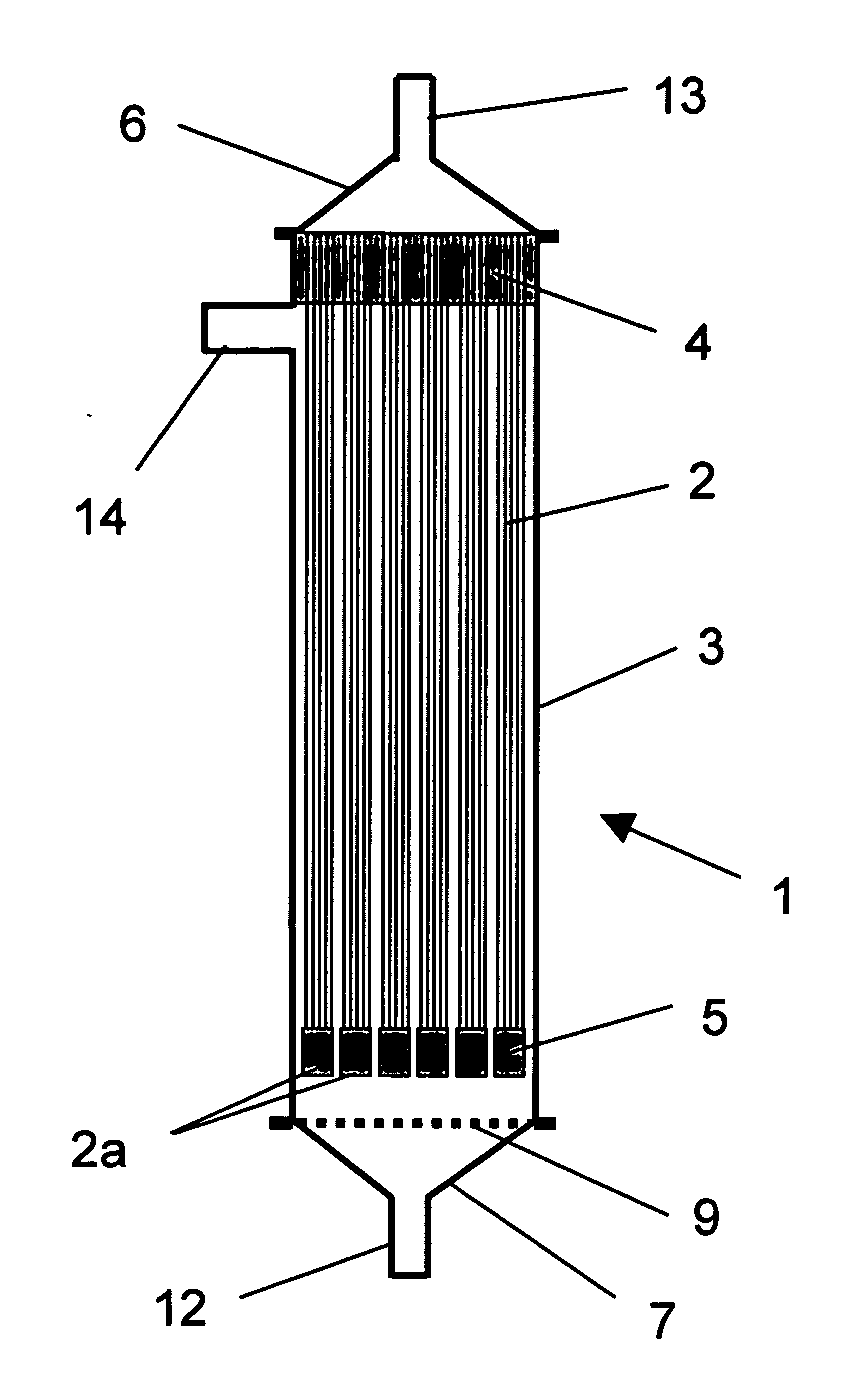
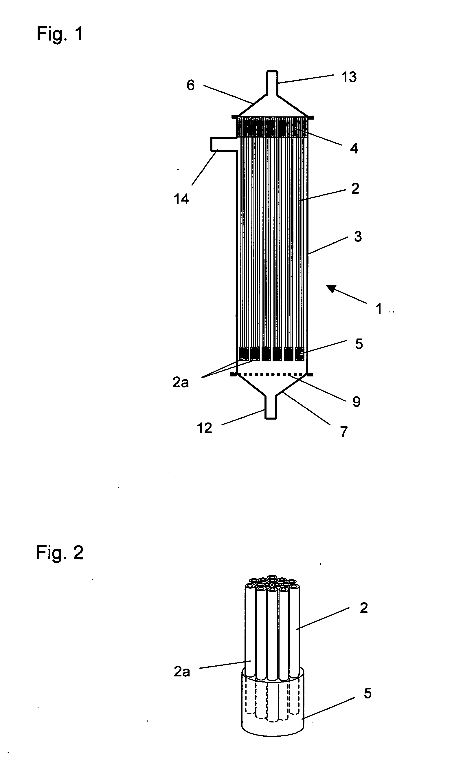
[0137]The hollow fiber membrane module 1 shown in FIG. 1 was used to filter water taken from Lake Biwa, followed by back washing, air scrubbing and discharge.
[0138]Lake water was supplied by a pump to the module 1 at 83 liters/m2·hr, and filtered for 30 minutes, and then 100 liters of the permeate was used to carry out back washing of the hollow fiber membranes 2. Air was blown into the module 1 through the inlet port 12 at 200 liters/min for 1 min, and then the water was discharged. This cycle of filtration, back washing, air scrubbing and discharge was performed repeatedly.
[0139]As the hollow fiber membranes 2, 9000 porous hollow fiber membranes made of polyvinylidene fluoride having an outer diameter of 1.5 mm, inner diameter of 0.9 mm and length of 1870 mm were used. A cylindrical case of polyvinyl chloride resin having an inner diameter of 193 mm and length 2000 mm was used as the cylindrical case 3.
[0140]Epoxy resin was used for the synthetic polymer resin (top end plate) 4 and the plugging member (small bundle forming member) 5. The plugging member (small bundle forming member) 5 used had a cylindrical shape, and bundled 420 to 430 of the hollow fiber membranes 2 into a small bundle 2a, and for each small bundle 2a, the ends of the hollow fiber membranes 2 were plugged with the epoxy resin.
[0141]The above-mentioned cycle of operations was performed repeatedly using the module 1 for 22 days, but the difference between the pressure in the cylindrical case 3 and that in the top cap 6 was always below 150 kPa.

Example

COMPARATIVE EXAMPLE 1
[0142]The same procedure as in Example 1 was carried out to repeat the cycle of filtration, back washing, air scrubbing and discharge except that both ends of the hollow fiber membranes 2 were fixed to the cylindrical case 3 with the synthetic polymer resin 4 as shown in FIG. 7.
[0143]The above-mentioned cycle of operations was performed repeatedly using the module 1, and the difference between the pressure in the cylindrical case 3 and that in the top cap 6 reached was 150 kPa on the 7th day.

Example

EXAMPLE 2
[0144]The same procedure as in Example 1 was carried out to repeat the cycle of filtration, back washing, air scrubbing and discharge except that the conditions were changed as described under (1) to (4) below, and the process of scale removal from the hollow fiber membranes 2 in the transparent case (see condition (2) describe below) was observed.

PUM

PropertyMeasurementUnit
Fraction0.25fraction
Diameter0.05 ~ 0.4m
Diameter0.5 ~ 3.0m
tensileMPa
Particle sizePa
strength10

Description & Claims & Application Information

We can also present the details of the Description, Claims and Application information to help users get a comprehensive understanding of the technical details of the patent, such as background art, summary of invention, brief description of drawings, description of embodiments, and other original content. On the other hand, users can also determine the specific scope of protection of the technology through the list of claims; as well as understand the changes in the life cycle of the technology with the presentation of the patent timeline. Login to view more.

Similar technology patents

Method for reducing amyloid beta concentration in blood

ActiveUS20120031840A1Efficiently removeSolvent extractionDialysisΒ amyloidRemove blood
Owner:SCHOOL JURIDICAL PERSON FUJITA EDUCATIONAL INSTITUTION +1

Thermal De-Scaling Surfaces With Cryogenic Liquids And Gases

InactiveUS20100132747A1Simplify design and operationEfficiently removeCleaning heat-transfer devicesCleaning apparatusSolid phasesPollutant
Owner:APPLIED CRYOGENIC SOLUTIONS

Lead-free solder, and connection lead and electrical component using said lead-free solder

InactiveUS7148426B2Efficiently breakEfficiently removePrinted circuit assemblingSingle bars/rods/wires/strips conductorsCopper tapeOxide
Owner:HITACHI CABLE

Classification and recommendation of technical efficacy words

  • Facilitate preventing
  • Efficiently remove

Seat height adjusting device for automobile

ActiveUS20090127907A1Facilitate preventingSimple constructionVehicle seatsSeating furnitureCar seatEngineering
Owner:TS TECH CO LTD

Vehicle air induction assembly

ActiveUS20210402871A1Facilitate preventingMachines/enginesAir intakes for fuelAutomotive engineeringMechanical engineering
Owner:NISSAN MOTOR CO LTD

Anhydrous processing of methane into methane-sulfonic acid, methanol, and other compounds

InactiveUS20080161591A1Increase solubility and reaction rateEfficiently removePeroxyhydrates/peroxyacidsOrganic compound preparationWaste productionSolvent
Owner:RICHARDS ALAN K

System, apparatus and method for opening an occluded lesion

InactiveUS20080319462A1Efficiently removeIncrease flexibilityCannulasGuide wiresRotational atherectomy deviceIntroducer sheath
Owner:CARDIOVASCULAR SYST INC

Tobacco free hookah smoking system

InactiveUS20140069446A1Efficiently removeDecrease in sizeCigar manufacturePretreated surfacesGrowstonesHookah Smoking
Owner:BEDROCK HLDG TRUST 2012
Why Eureka
Try Eureka