Device for depositing individual printed products, supplied in succession, in shingle formation

a technology for printing products and shingle formation, which is applied in the direction of thin material processing, function indicators, articles, etc., can solve the problems of short drop time and no longer produced faulty shingle formation, and achieve high processing speed, reliable and flawless depositing of thicker and/or less flexible printed products, the effect of small format length

Inactive Publication Date: 2007-07-19
KOLBUS
View PDF11 Cites 18 Cited by
  • Summary
  • Abstract
  • Description
  • Claims
  • Application Information

AI Technical Summary

Benefits of technology

[0008]The present embodiment is based on the objective of developing a device for depositing individual printed products, supplied in succession, in shingle formation, wherein said device should also make it possible to reliably and flawlessly deposit thicker and / or less flexible printed products at high processing speeds. It should be possible, in particular, to reliably deposit printed products with short dimensions referred to the shingle spacing if changes in the transport speed occur.
[0009]According to the embodiment, this objective is attained by reducing the compartments known from the fan wheel feed to relatively short pockets such that the printed products also quickly come in contact with the bottom stop of the pockets if the difference between the feed speed and the speed of the rotating grippers is relatively small. This is particularly beneficial when processing small format lengths and less flexible printed products. In order to ensure that the printed products aligned on the bottom stop can no longer be displaced during their additional transport and are therefore transferred in a precisely positioned fashion, the printed products are subsequently transported while being taken hold of and deflected approximately in the stream feeding direction of the downstream conveyor during this process. The grippers are opened before the stripping element is reached, wherein the printed products drop on the downstream conveyor in the direction of the product thickness along the shortest path possible due to the centrifugal force and the downwardly acting weight. The dropping time therefore is so short that a faulty shingle formation is no longer produced, namely even if significant speed changes occur. In addition, the stripping element ensures that the printed products are reliably removed from the pocket of the opened gripper. To sum up, the printed products supplied with a high speed practically are reliably and carefully decelerated to the stream feeding speed in several successive deceleration processes.
[0010]The embodiment allows a constant rotational speed of the grippers such that a simple construction of the device is achieved and no relative speed occurs between the printed products transported while being taken hold of by a gripper and the supporting disk. A format adjustment with respect to the format length of the printed products can be easily realized by turning the control cam. In order to achieve a trouble-free operation with high processing speeds, the trailing edge is displaced out of the moving path of the following printed product due to the deflection of the printed products by a defined angle in the stream feeder during the transport phase in which the printed products are taken hold of by the grippers. A constant shingle spacing is preferably realized during the depositing or dropping of the printed products in cooperation with pushers that are arranged at fixed distances from one another on the downstream conveyor.

Problems solved by technology

The dropping time therefore is so short that a faulty shingle formation is no longer produced, namely even if significant speed changes occur.

Method used


Image

  • Device for depositing individual printed products, supplied in succession, in shingle formation
  • Device for depositing individual printed products, supplied in succession, in shingle formation

Examples


Embodiment Construction

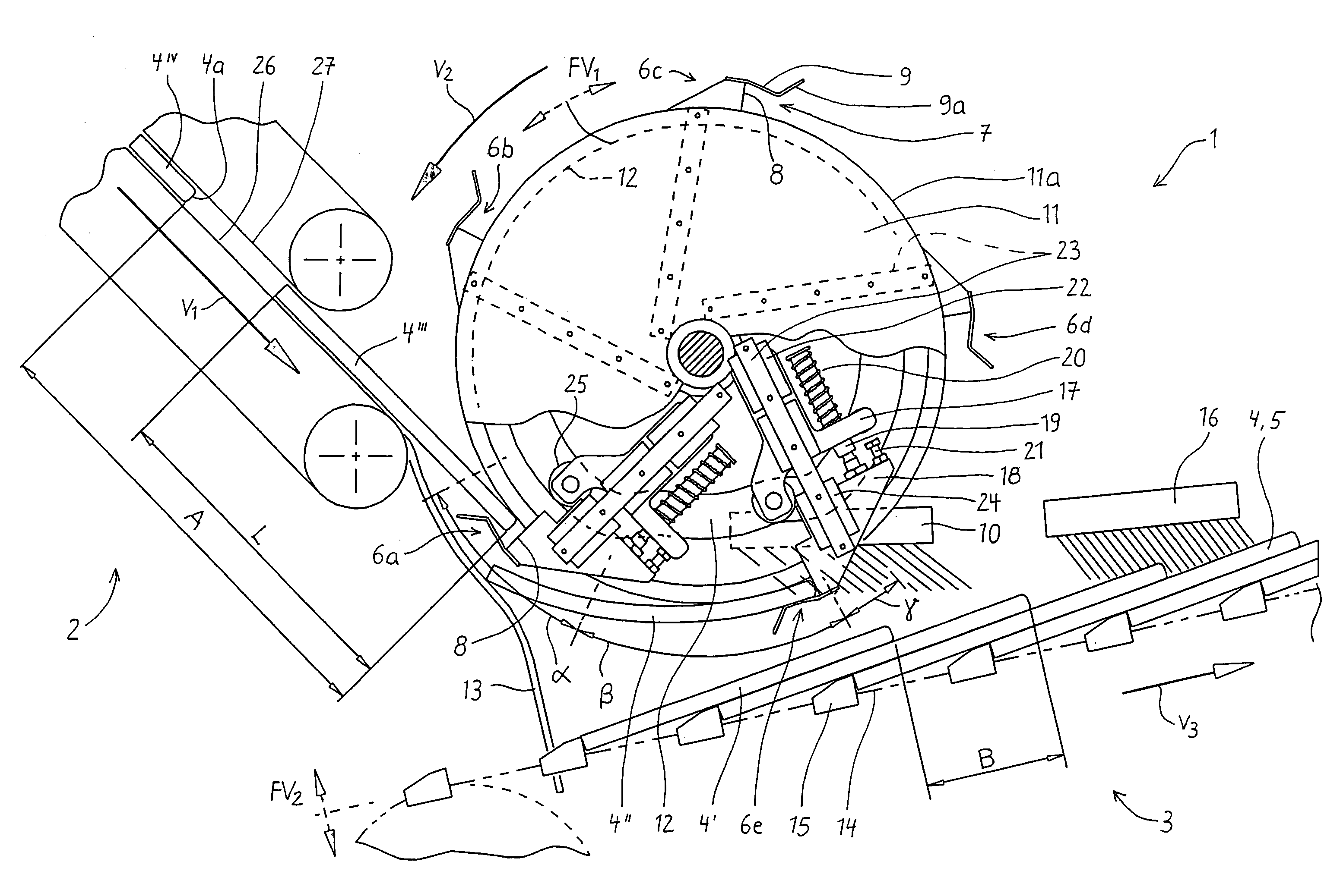
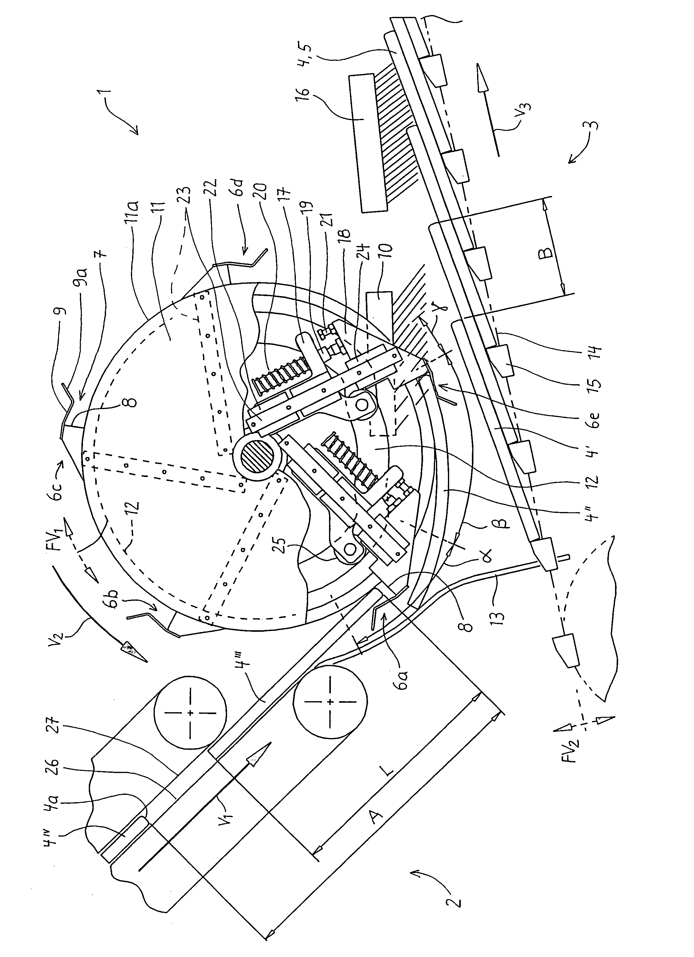
[0012]The FIGURE shows a partially schematic side view of a stream feeder 1 for depositing individual brochures 4 (4I, 4II, 4III, 4IV), supplied in succession by means of a feed conveyor 2, on a downstream conveyor 3 with a slower transport speed v3 in shingle formation 5. The brochures 4 have a format length L and are successively transported obliquely downward with a feed speed v1 by the feed conveyor 2 that clamps the brochures 4 between conveyor belts 26, 27 such that they are spaced apart from one another by a distance A, wherein the brochures are then fed to the stream feeder 1 with their spine 4a pointing forward. The bottom conveyor belt 26 extends slightly farther than the upper conveyor belt 27 such that the brochures 4 are provided with a supporting surface.

[0013]The stream feeder 1 features a plurality of rotating grippers 6a to 6e that are continuously driven in a rotative fashion with a constant gripper speed v2. The grippers 6a to 6e are respectively realized in the f...


PUM

PropertyMeasurementUnit
feed speedaaaaaaaaaa
transport speedaaaaaaaaaa
distanceaaaaaaaaaa

Abstract

A device for depositing individual printed products (4), preferably magazines, brochures or book blocks, that are supplied in succession by means of a feed conveyor (2) on a downstream conveyor (3) with slower transport speed (v3) in shingle formation (5), wherein said device comprises a stream feeder (1) that receives the printed products (4) from the feed conveyor (2) by means of rotating grippers (6a to e) that are opened and closed in the appropriate cycle with the aid of a stationary cam (12) and deposits the printed products on the downstream conveyor (3). In order to reliably and flawlessly deposit the printed products, particularly thick and / or less flexible printing products, in shingle formation, the stream feeder includes a plurality of grippers (6a to e) that are rotatively driven with a slower speed (v2) than the feed speed (v1), wherein the grippers (6a to e), opened for receiving the printed products, respectively include a short pocket (7) with a bottom stop (8), with which the respectively supplied printed product (4) comes in contact due to the higher feed speed (v1). The clamped transport takes place within an angular range (β) of the rotational movement of the grippers, namely up to a defined distance upstream of a stripping element (10) for reliably releasing the printed products (4). They drop on the downstream conveyor (3) along a short path.

Description

TECHNICAL FIELD [0001]This disclosure pertains to a device for depositing individual printed products that are supplied in succession in shingle formation.BACKGROUND OF THE INVENTION [0002]DE 198 46 032 C2 describes devices for depositing flat objects such as tubular sections or bags consisting of paper, wherein the supplied objects are decelerated with a device that settles on the deposited objects from the top. Devices of this type are also suitable for depositing thicker printed products in shingle formation, e.g., magazines, brochures or book blocks. The objects are transported with a relatively high speed on a conveyor belt while being spaced apart from one another and transferred to an obliquely ascending downstream conveyor belt that revolves with a slower speed. In order to produce the shingle formation, the supplied objects are decelerated by one or more deceleration rolls that are rotatably supported on swiveling levers and roll on the shingle formation being produced with...

Claims


Application Information

Patent Timeline
Patent Type & Authority Applications(United States)
IPC IPC(8): B65H29/06
CPCB65H29/06B65H29/40B65H29/6609B65H2301/44714B65H2301/44732B65H2301/4474B65H2404/655B65H2220/01B65H2220/02
Inventor BROMMER, CARSTEN
Owner KOLBUS
Why Eureka
Try Eureka