Timing controller for liquid crystal display

a technology of liquid crystal display and time controller, which is applied in the direction of static indicating devices, instruments, cathode-ray tube indicators, etc., can solve the problems of affecting and achieve the effect of improving the image quality of the liquid crystal display device and stable display

a technology of liquid crystal display and time controller, which is applied in the direction of static indicating devices, instruments, cathode-ray tube indicators, etc., can solve the problems of affecting and achieve the effect of improving the image quality of the liquid crystal display device and stable display

US20070164969A1Active Publication Date: 2007-07-19SAMSUNG DISPLAY CO LTD

Image

  • Timing controller for liquid crystal display
  • Timing controller for liquid crystal display
  • Timing controller for liquid crystal display

Examples


Embodiment Construction

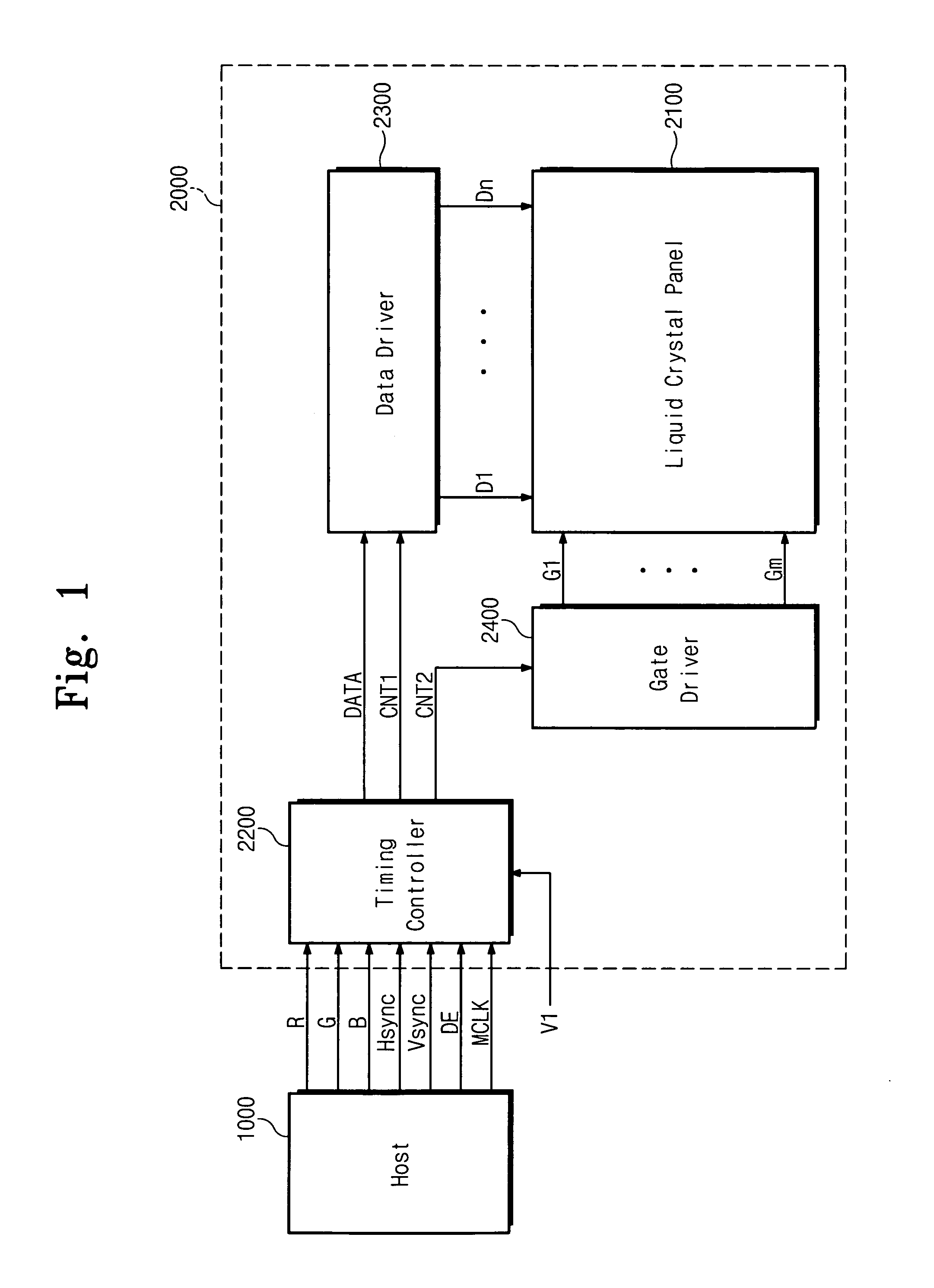
[0016] Referring to FIG. 1, the display system includes a host 1000 providing image data signals RGB and control signals such as a horizontal synchronous signal Hsync, a vertical synchronous signal Vsync, a data enable signal DE and a main clock signal MCLK to a liquid crystal display device 2000. Host 1000 includes a graphic card used for a computer and provides the image data signals RGB to be displayed on liquid crystal display device 2000. The image data signals RGB and the control signals Hsync, Vsync, DE and MCLK are transmitted between host 1000 and liquid crystal display device 2000 through a low voltage differential signal (LVDS) interface or a transistor-to-transistor logic (TTL) interface.

[0017] Liquid crystal display device 2000 includes a liquid crystal panel 2100 displaying the images, a timing controller 2200 generating control signals, a data driver 2300 outputting data line driving signals, and a gate driver 2400 outputting gate line driving signals.

[0018] Liquid ...


PUM


Abstract

A timing controller for a liquid crystal display device includes an error detection module that detects an error in signals input from an external source and generates a data signal based on the error in the signals, so as to display the data signal on a liquid crystal panel for a predetermined time period. Thus, the liquid crystal display device stably displays the data signal while compensating for the error in the input signals, thereby improving the image quality of the liquid crystal display device.

Description

CROSS-REFERENCE TO RELATED APPLICATION [0001] This application relies for priority upon Korean Patent Application No. 2006-11848 filed on Feb. 7, 2006, the contents of which are herein incorporated by reference in its entirety. [0002] 1. Field of the Invention [0003] The present invention relates to a liquid crystal display device and, more particularly, to a timing controller capable of detecting an error in an input signal. [0004] 2. Description of the Related Art [0005] Together with display devices employing cathode ray tubes, liquid crystal display devices occupy an important position in the field of image display devices. The liquid crystal display device includes two separated substrates with a liquid crystal layer between them. The liquid crystal display device applies an electric field to the liquid crystal panel by varying the applied electric field to control the transmittance of light passing through the liquid crystal layer. If the image data signal and the control sign...

Claims


Application Information

Patent Timeline
19 Jul 2007
Publication
US20070164969A1
IPC
G09G3/36
CPC
G09G3/3611; G09G5/008; G09G5/006
Inventors
KIM, MYEONG-SU