Liquid-jet head and liquid-jet apparatus

Active Publication Date: 2007-07-19
SEIKO EPSON CORP
View PDF4 Cites 19 Cited by
  • Summary
  • Abstract
  • Description
  • Claims
  • Application Information

AI Technical Summary

Benefits of technology

[0018] Furthermore, the reinforcing portion disposed at the clearance defined between the head bodies may be constituted of a first layer formed on the side of the fixing member and a second layer formed on the first layer and made of an adhesive agent having a higher hardness in a set state than the adhesive agent constituting the first layer, and further, the reinforcing portion disposed at the circumferential edge of the fixing member may be constituted of only the first layer. This makes it possible to more securely prevent any deformation of the fixing plate caused by the abutment of the capping member or the like, and further, to prevent any deformation of the fixing plate accompanied with the setting contraction of the adhesive agent constituting the reinforcing portion.
[0019] Moreover, a liquid-jet head further may include a joining member, which joins each of the plurality of head bodies thereto and is formed integrally with a plurality of paths corresponding to the head bodies, respectively, on the side of the head case in each of the head bodies. In this case, it is preferable that the recess portion formed in the fixing member should have a depth reaching the joining member at the tip of the side wall. In this manner, the deformation of the fixing member can be restricted by the effect of the abutment of the side wall against the joining member.
[0020] Additionally, a pair of cutout portions for exposing a part of each of both ends of the head body may be formed on the side wall of the fixing member in a manner corresponding to each of the head bodies. This allows a part of the head body to be exposed from the cutout portion in the state that the head bodies are mounted on the fixing member. Thus, the cutout portion holds and moves the head body, so that the

Problems solved by technology

As a consequence, when the capping member abuts against an ink ejection surface in the ink-jet recording head, the fixing plate is deformed (curved), thereby inducing a possibility of misalignment of the nozzles.
Here, if the nozzles are misaligned, the l

Method used


Image

  • Liquid-jet head and liquid-jet apparatus
  • Liquid-jet head and liquid-jet apparatus
  • Liquid-jet head and liquid-jet apparatus

Examples


first embodiment

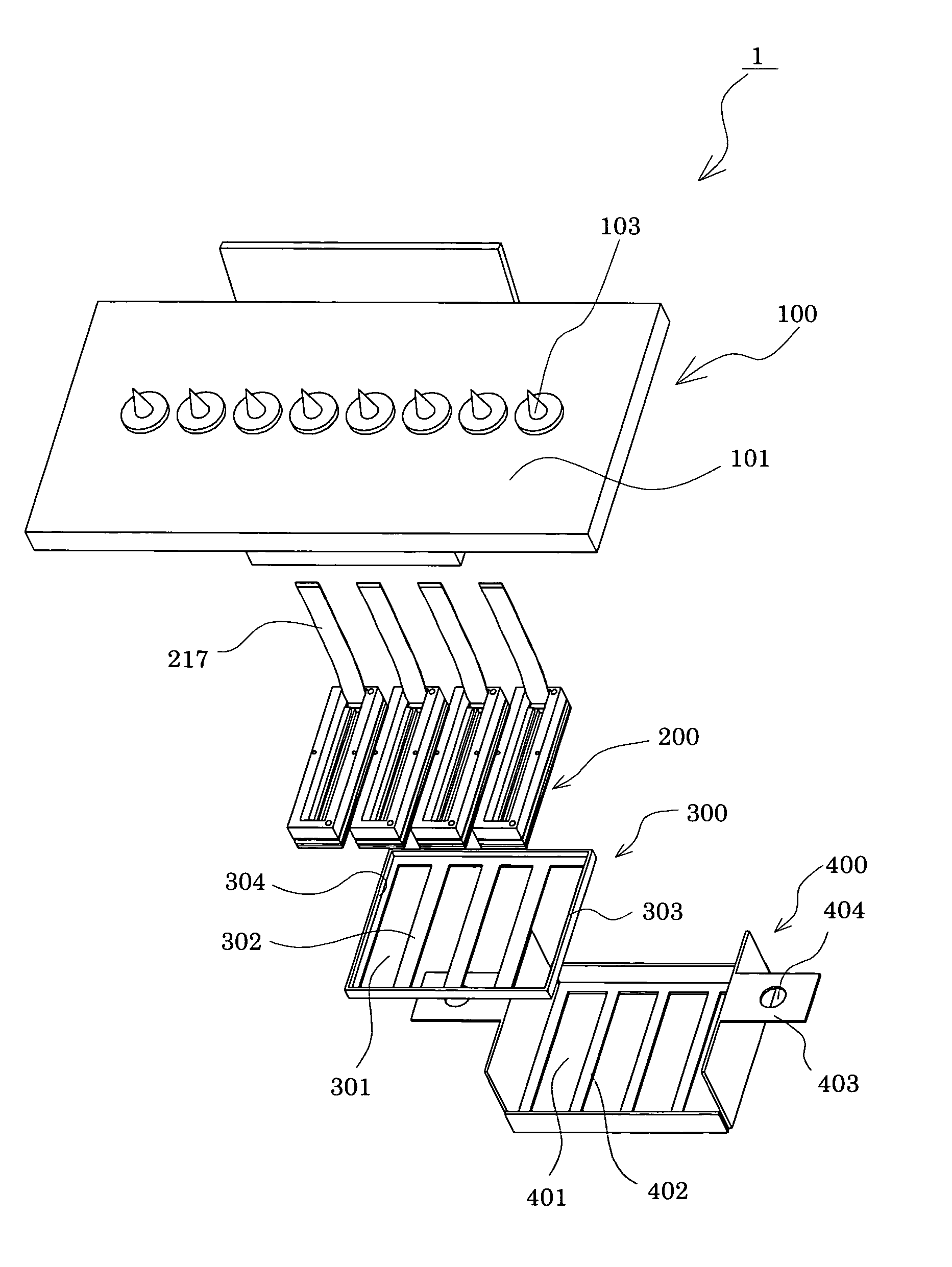
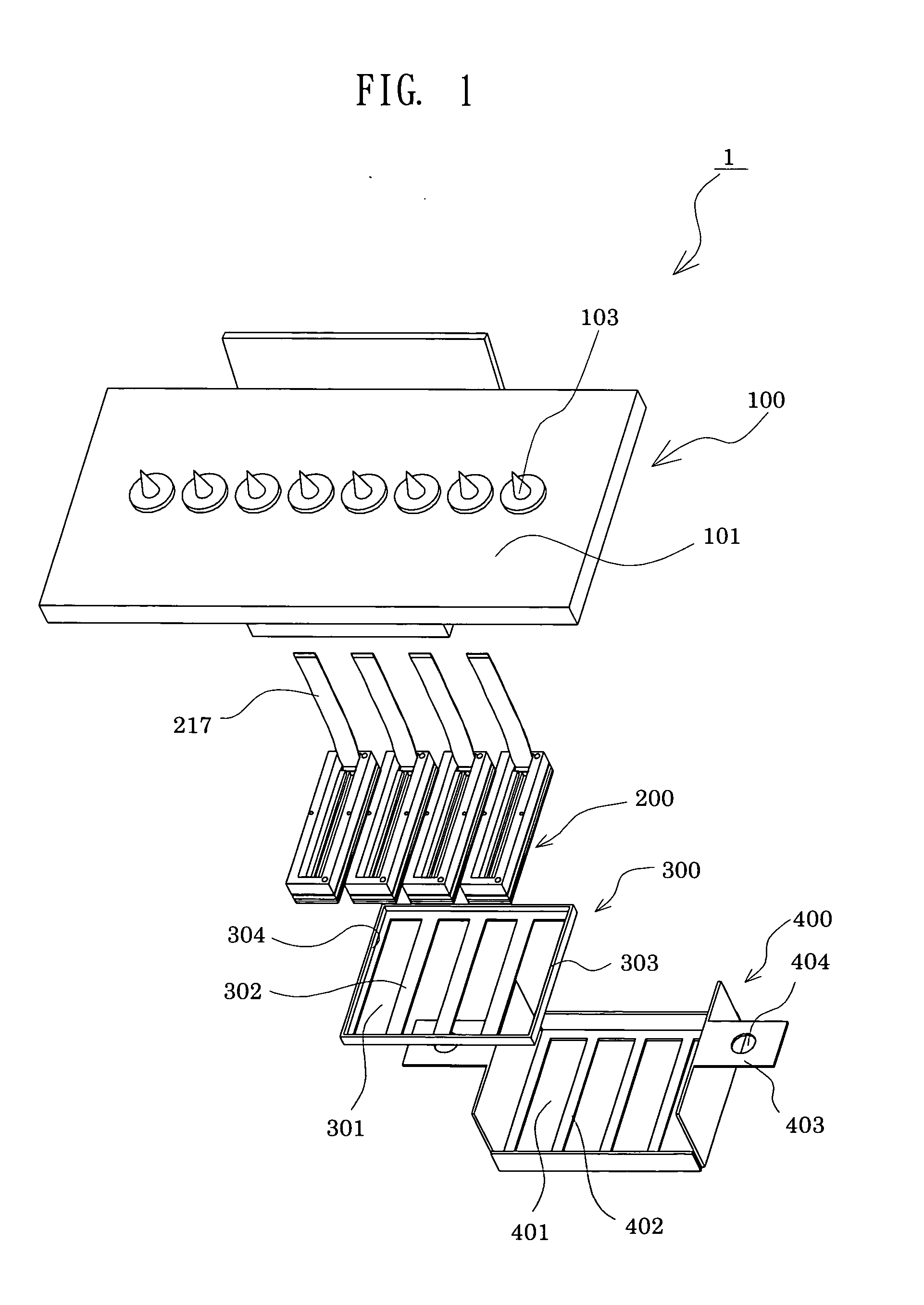
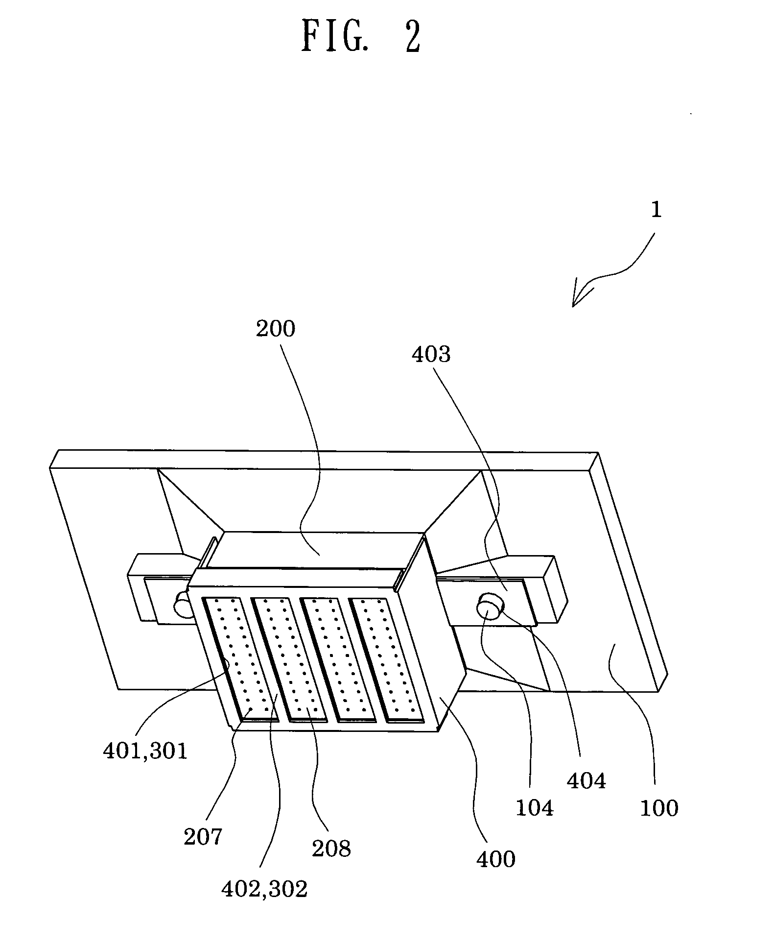
[0038]FIG. 1 is an exploded perspective view showing an ink-jet recording head according to a first embodiment according to the invention; FIG. 2 is an assembled perspective view showing the ink-jet recording head; and FIG. 3 is a cross-sectional view showing essential parts of the ink-jet recording head.

[0039] An ink-jet recording head 1 (hereinafter simply referred to as “recording head”) shown in FIGS. 1 to 3 is constituted of a cartridge case 100 serving as a joining member; ink-jet recording head bodies 200 (hereinafter simply referred to as “recording head bodies”); a fixing plate 300 serving as a fixing member which is bonded to a nozzle plate 208 so as to positionally fix the plurality of recording head bodies 200 thereto; and a cover head 400. The cartridge case 100 is made of, for example, a resin material, and includes a cartridge disposing portion 101 on which ink cartridges (not shown) serving as ink suppliers (liquid suppliers) are disposed. Formed at the bottom of th...

second embodiment

[0063]FIG. 8 is a cross-sectional view showing essential parts of a recording head according to a second embodiment. The configuration in the second embodiment is identical to that in the first embodiment except that the configuration of a reinforcing portion is varied. Specifically, the reinforcing portion 230 in the first embodiment is made of one and the same adhesive agent over the entire region in the thickness direction: in contrast, a reinforcing portion 230A in the second embodiment is constituted of two layers, that is, a first layer 231 and a second layer 232 made of different adhesive agents, as shown in FIG. 8. In the case where the reinforcing portion 230A is constituted of the first layer 231 and the second layer 232, an adhesive agent constituting the first layer 231 formed on a side of a fixing plate 300 is higher in hardness in a set state than an adhesive agent constituting the second layer 232. In other words, the layers constituting the reinforcing portion 230A a...

third embodiment

[0069]FIG. 10 is a schematic view explanatory of a reinforcing portion forming position according to a third embodiment. The configuration of a reinforcing portion is varied in the present embodiment, in which various adhesive agents are used according to reinforcing portion forming regions. The configuration is identical to that of the first embodiment except for the configuration of the reinforcing portion.

[0070] A reinforcing portion 230D according to the third embodiment includes a first reinforcing portion 233 disposed between a bent portion 303 and each of recording head bodies 200, that is, at a circumferential edge of a fixing plate 300 and a second reinforcing portion 234 disposed at a clearance defined between the recording head bodies 200, as shown in FIG. 10. The first reinforcing portion 233 is made of an adhesive agent having a higher hardness in a set state than an adhesive agent forming the second reinforcing portion 234. For example, in the third embodiment, the fi...


PUM


Abstract

A liquid-jet head includes: a plurality of head bodies, each having: a nozzle plate having a plurality of nozzles bored therein; a passage-forming substrate having a pressure generating chamber formed therein, which communicates with the nozzle and receives a pressure for use in ejecting a liquid droplet from a pressure generating element; and a head case disposed on the passage-forming substrate at a surface opposite to the nozzle plate and having paths for supplying liquid to the pressure generating chamber therethrough; and a fixing member bonded onto a side of the nozzle plate of each of the plurality of head bodies, to positionally fix the head bodies thereto at predetermined intervals, wherein a reinforcing portion made of a predetermined adhesive agent, which is charged in a clearance between the head bodies fixed to the fixing member, followed by setting, is disposed at the clearance.

Description

[0001] The entire disclosure of Japanese Patent Applications Nos. 2006-11630 filed Jan. 19, 2006 and 2006-343584 filed Dec. 20, 2006 is expressly incorporated by reference herein. BACKGROUND [0002] 1. Technical Field [0003] The present invention relates to a liquid-jet head and a liquid-jet apparatus which jet a liquid droplet from a nozzle bored at a nozzle plate. In particular, the invention relates to an ink-jet recording head and an ink-jet recording apparatus, in which an ink droplet is ejected from a nozzle in accordance with an amount of displacement of a piezoelectric element mounted on a vibration plate constituting a part of a pressure generating chamber communicating with the nozzle. [0004] 2. Related Art [0005] There has been conventionally known a liquid-jet head which ejects a liquid droplet from a nozzle by applying a pressure to liquid by a piezoelectric element or a pressure generator such as a heat generating element. Atypical example of the liquid-jet head include...

Claims


Application Information

Patent Timeline
IPC IPC(8): B41J2/16
CPCB41J2/14024B41J2002/14362B41J2/14233
Inventor HONMA, HIROKIGOTO, KAZUTOSHIYANAGISAWA, ISAOOWAKI, HIROSHIGE
Owner SEIKO EPSON CORP
Why Eureka
Try Eureka