Alignment system and method

Inactive Publication Date: 2007-07-19
ONDINE INT
View PDF7 Cites 4 Cited by
  • Summary
  • Abstract
  • Description
  • Claims
  • Application Information

AI Technical Summary

Benefits of technology

[0006] The present invention overcomes the above-discussed disadvantages associated with the conventional alignment techniques. The present invention has the unique capability of being assembled with physical clamping techniques such as screws that allow for a stable assembly but can still be removed for rework, testing or upgrading. It does not generally require expensive, high precision positioning equipment and tooling to conduct the alignment procedure. The present invention does not require limited physical overlap

Problems solved by technology

Most of the conventional techniques are permanent, meaning that attempts to disassemble them can cause permanent damage to some of the components.
They also are likely to require expensive, high precision positioning equipment and tooling to conduct the alignment procedure.
Finally, although many of the conventional techniques can produce well-aligned assemblies, they often suffer from limited strength due to limited physical overlap of the welded or bonded components.
However, during the cure, out-gassing can damage components and many adhesives shrink when curing, potentially destroying a high precision alignment.
Adhesives also have many potential durability issues.
Humidity and temperature effects ca

Method used


Image

  • Alignment system and method
  • Alignment system and method
  • Alignment system and method

Examples


Embodiment Construction

[0030] The above-described drawing figures illustrate the present invention in at least one of its preferred, best mode embodiments, which is further defined in detail in the following description. Those having ordinary skill in the art may be able to make alterations and modifications in the present invention without departing from its spirit and scope. Therefore, it must be understood that the illustrated embodiments have been set forth only for the purposes of example and that they should not be taken as limiting the invention as defined in the following.

The Alignment System

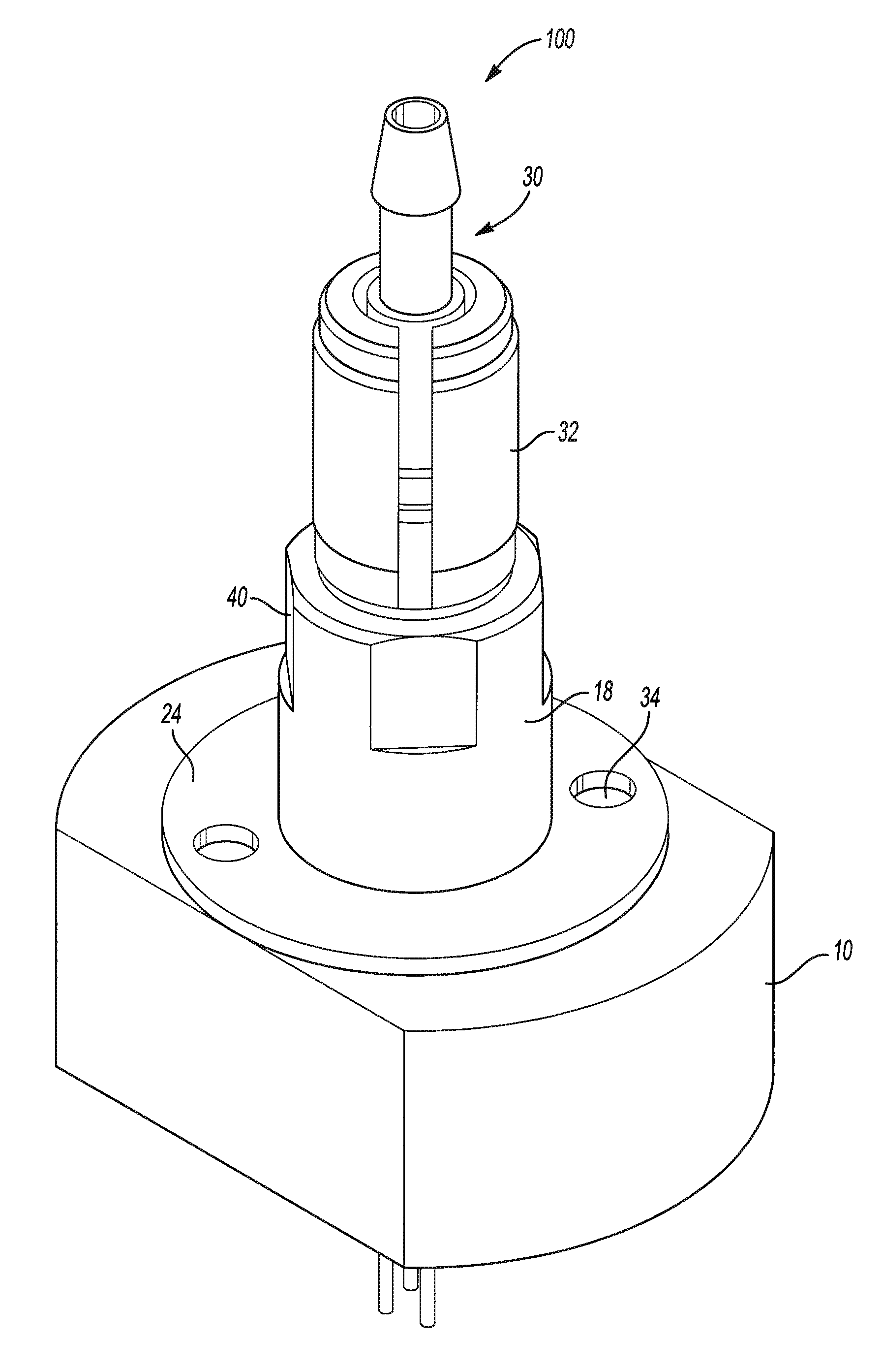
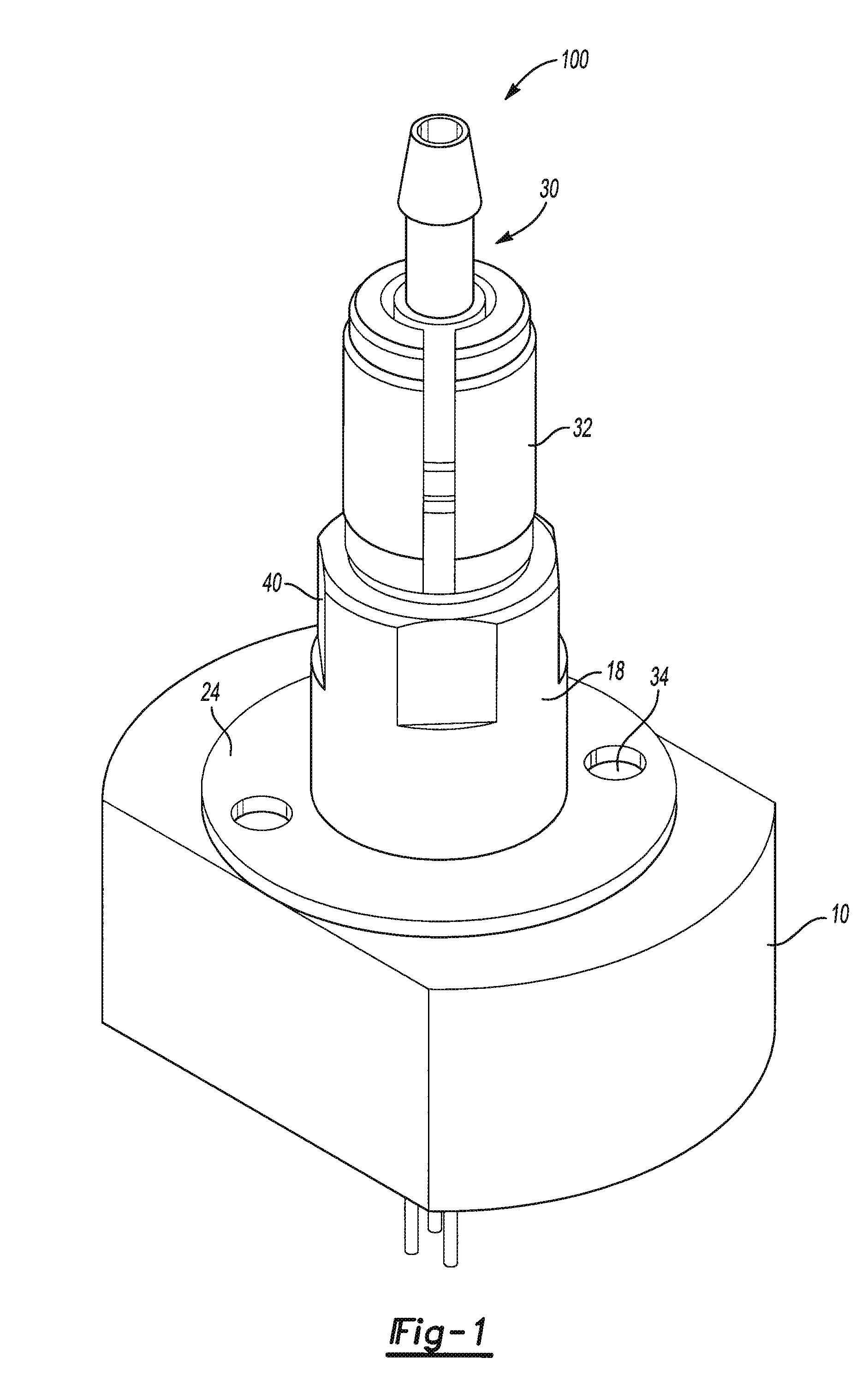
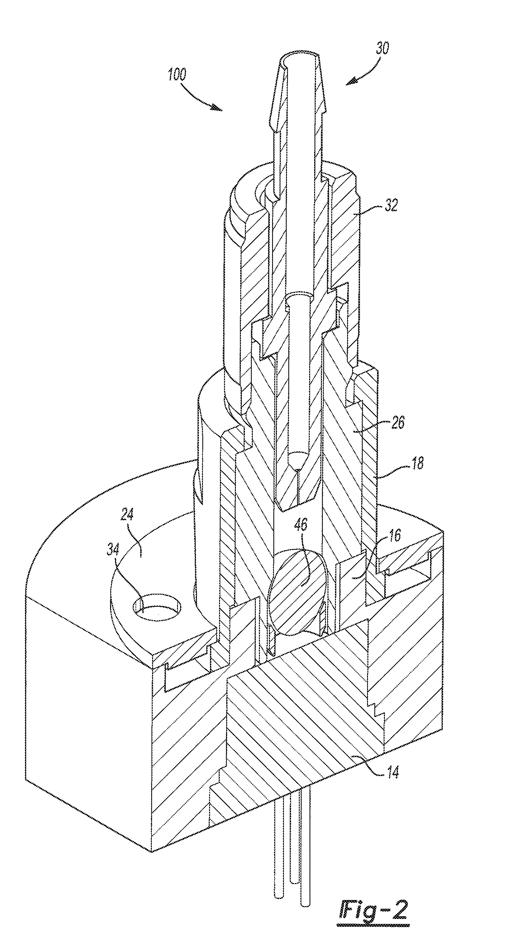
[0031] Referring to FIGS. 1-7 the present invention provides an alignment system 100 comprising the following components: a base 10 having a feature (e.g., first through hole 12 as shown in FIGS. 1-7) that accepts a first optical element 14; a first eccentric element 18 having a second through hole 20 that accepts an eccentric assembly 22, the first eccentric element 18 engaged with the base 10 via first at...


PUM


Abstract

The present invention provides an alignment system comprising a base having a feature that accepts a first optical element, a first eccentric element having a through hole that accepts an eccentric assembly comprising a second eccentric element having a feature that accepts a second optical element and is attached to the second optical element via second attachment means, wherein the first eccentric element is engaged with the base via first attachment means and axial alignment between optical axis of the first optical element and optical axis of the second optical element is achieved by rotationally adjusting at least one of the eccentric elements relative to the base. The present invention also provides methods to make and use this alignment system.

Description

CLAIM OF BENEFIT OF FILING DATE [0001] This application claims the benefit of U.S. Provisional Application Ser. No. 60 / 729,626 titled: “Alignment System and Method” filed on Oct. 25, 2005.FIELD OF INVENTION [0002] This invention is intended to serve as a mechanism for aligning a set of components and holding them in an aligned state. Specifically, this invention is intended to provide a system and a method for aligning the axis of at least two optical components, such as a stable alignment between an optical fiber and a laser diode, two optical fibers, or the like. BACKGROUND OF INVENTION [0003] A typical method of aligning an optical fiber with a laser diode involves a single base unit that has an oversized hole that accepts the laser diode on one side and a fiber optic ferrule on the other. The fiber ferrule is often affixed to the base using a method such as clamping, gluing, welding, etc. Alignment is accomplished by moving the laser diode around in the oversized hole, often wit...

Claims


Application Information

Patent Timeline
IPC IPC(8): G02B6/36
CPCG02B6/4204G02B6/4292G02B6/4236G02B6/4234G02B6/32G02B6/42
Inventor ROSE, ANDREASHERR, GUENTERJOHNSTON, KYLE
Owner ONDINE INT
Why Eureka
Try Eureka