
Chemical liquid injection system

a liquid injection system and liquid syringe technology, applied in instruments, other medical devices, sensing record carriers, etc., can solve the problems of medical malpractice, inability to prevent medical malpractice of reuse of liquid syringes, and inability to prevent improper use of syringe peripheral tools such as extension tubes and catheters

Active Publication Date: 2007-07-19
NEMOTO KYORINDO KK
View PDF5 Cites 91 Cited by
  • Summary
  • Abstract
  • Description
  • Claims
  • Application Information

AI Technical Summary

Benefits of technology

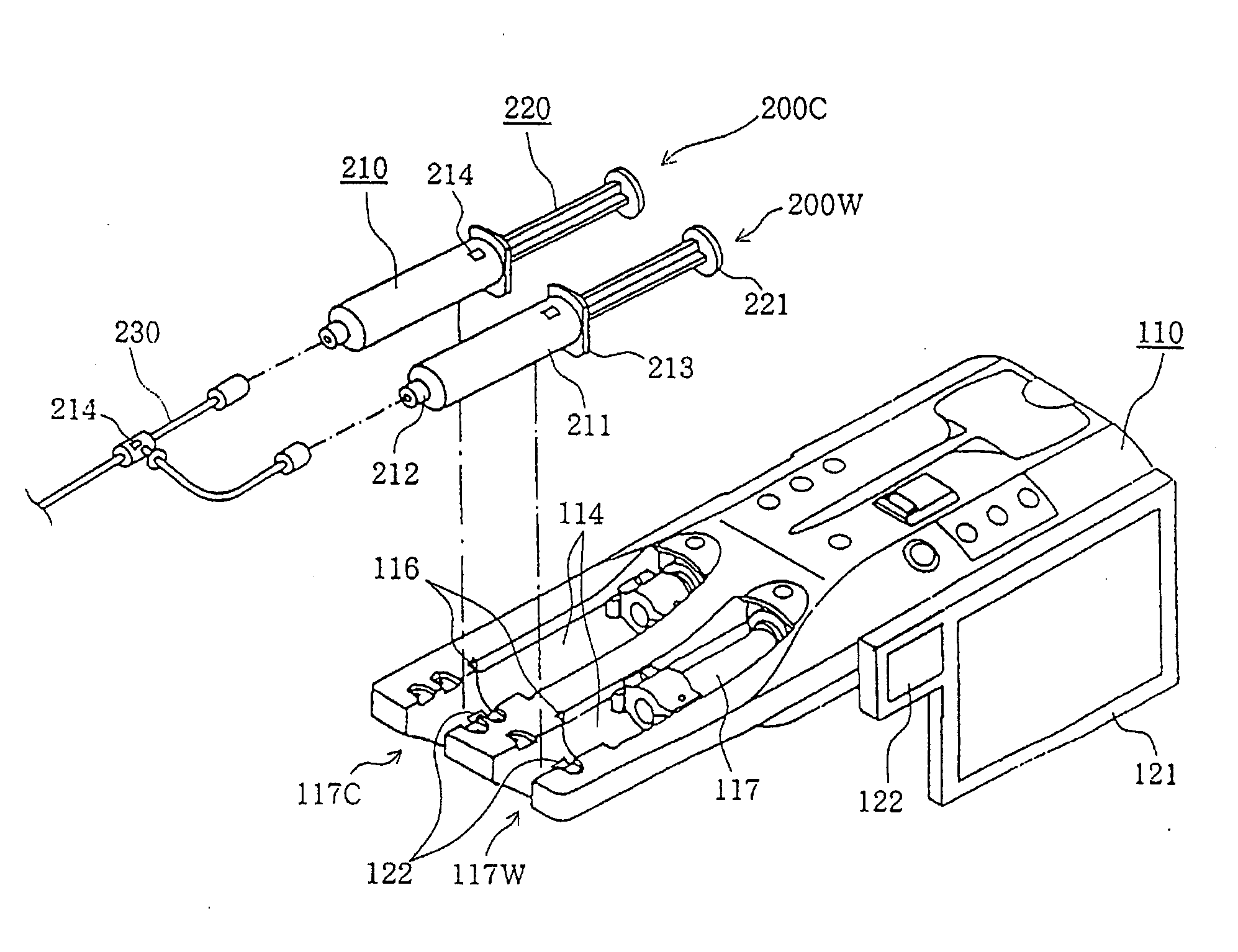
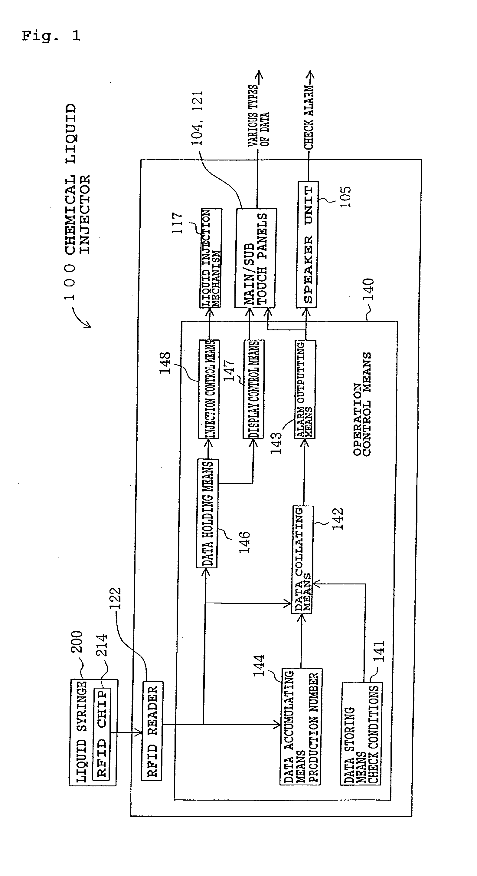
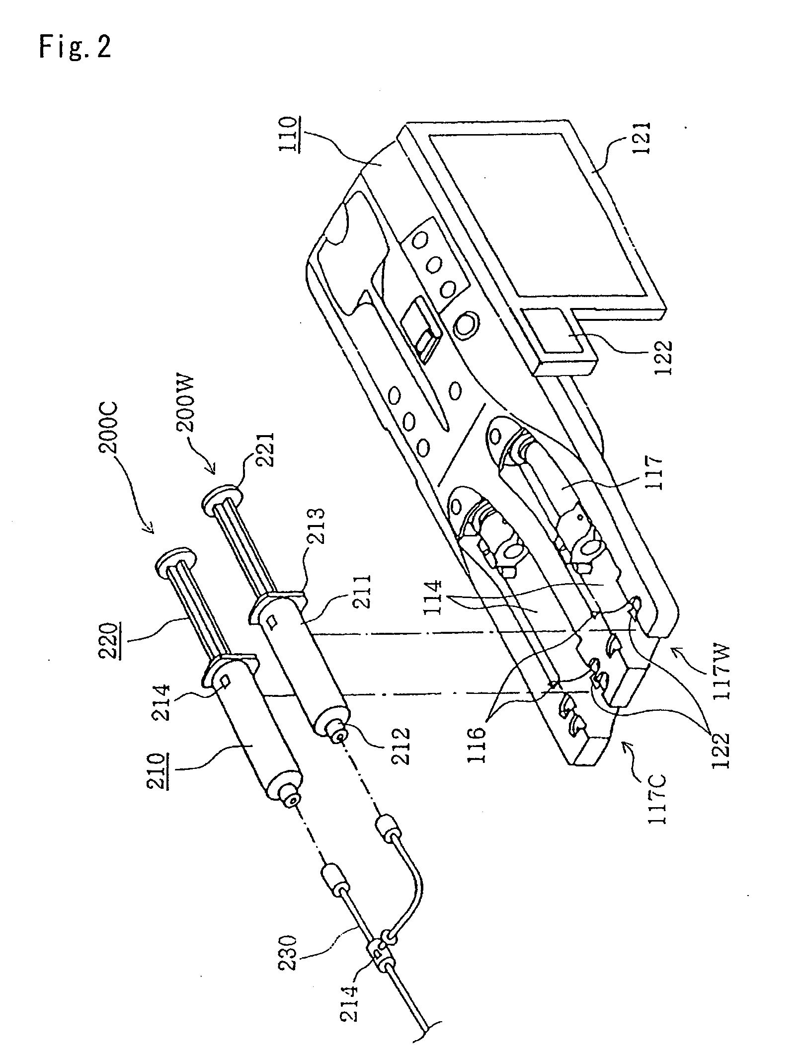
[0024] In the chemical liquid injection system of the present invention, the RFID chip having the various types of data recorded thereon is put on the liquid syringe. The chemical liquid injector obtains the various types of data recorded on the RFID chip and performs the predetermined operation in accordance with at least some of the various types of data. The variable pattern for the liquid, for example, can be recorded on the RFID chip of the liquid syringe to allow the chemical liquid injector to inject the liquid in accordance with the predetermined variable pattern. In this manner, a large amount of data can be easily input to the chemical liquid injector to perform the various operations.

Problems solved by technology

However, some liquid syringes have the same exterior appearance even when they contain different types of liquid, so that the operator may set a liquid syringe containing an inappropriate liquid on the chemical liquid injector.
In some cases, improperly manufactured liquid syringes may be used, and their inappropriate performance such as low resistance to pressure may cause medical malpractice.
For the currently available chemical liquid injectors, however, it is impossible to prevent medical malpractice of reuse of a liquid syringe after it is used once.
It is thus necessary to use a liquid syringe, an extension tube and the like resistant to the high pressure in the chemical liquid injector, but it is impossible to prevent the use of an improper product as a peripheral tool for the syringe such as the extension tube and the catheter.

Method used


Image

  • Chemical liquid injection system
  • Chemical liquid injection system
  • Chemical liquid injection system

Examples


embodiment

Configuration of Embodiment

[0053] An embodiment of the present invention will hereinafter be described with reference to drawings. As shown in FIGS. 1 to 4, chemical liquid injection system 1000 of the embodiment according to the present invention comprises chemical liquid injector 100, liquid syringe 200, and MRI apparatus 300 which is a diagnostic imaging apparatus. The system is provided for injecting a contrast media or the like as a liquid into a patient (not shown), as later described in detail.

[0054] As shown in FIG. 3, MRI apparatus 300 includes diagnostic imaging unit 301 serving as a mechanism for performing imaging and imaging control unit 302 such that diagnostic imaging unit 301 and imaging control unit 302 are wire-connected through communication network 303. Diagnostic imaging unit 301 shoots a diagnostic image of a patient. Imaging control unit 302 controls the operation of diagnostic imaging unit 301.

[0055] As shown in FIG. 5, liquid syringe 200 comprises cylinder...


PUM


Abstract

RFID chip (214) having various types of data is mounted on liquid syringe (200). Chemical liquid injector (100) obtains the various types of data from RFID chip (214) to perform a predetermined operation in accordance with at least some of the various types of data. For, example, a variable pattern for liquid can be recorded on RFID chip (214) of liquid syringe (200) to allow chemical liquid injector (100) to inject the liquid in accordance with the predetermined variable pattern. Thus, a large amount of data can be easily input to the chemical liquid injector to perform the various operations.

Description

TECHNICAL FIELD [0001] The present invention relates to a chemical liquid injection system in which a chemical liquid injector injects a liquid in a liquid syringe into a patient, and more particularly, to a chemical liquid injection system for injecting a contrast medium into a patient whose diagnostic images are to be taken by a diagnostic imaging apparatus such as a CT (Computed Tomography) scanner. BACKGROUND ART [0002] Presently available diagnostic imaging apparatuses for capturing diagnostic images of patients include CT scanners, MRI (Magnetic Resonance Imaging) apparatuses, PET (Positron Emission Tomography) apparatuses, ultrasonic diagnostic apparatuses, CT angiography apparatuses, and MRA (MR angiography) apparatuses. When such a diagnostic imaging apparatus is used, a liquid such as a contrast medium or physiological saline may be injected into a patient. Chemical liquid injectors for automatically performing the injection have been put into practical use. [0003] Such a ...

Claims


Application Information

Patent Timeline
IPC IPC(8): A61M5/00A61M3/00A61M5/14A61M5/145
CPCA61M2205/505A61M2205/581A61M5/1408A61M2205/583A61M5/1456A61M5/007A61M2205/6054A61M5/14546A61M2205/6018A61M5/1452A61M2205/60A61M2205/6009A61M2205/18A61M2205/33A61M2205/36A61M2205/50G06K7/10366
Inventor NEMOTO, SHIGERUTANO, NOBUHISA
Owner NEMOTO KYORINDO KK
Learn More