Cycle rate control algorithm

a technology of cycle rate and control algorithm, which is applied in the direction of instruments, heating types, static/dynamic balance measurement, etc., can solve the problems of lowering the efficiency of cooling or heating units, not being flexible, and limited approach

Active Publication Date: 2007-07-19
COMPUTIME LIMITED
View PDF22 Cites 12 Cited by
  • Summary
  • Abstract
  • Description
  • Claims
  • Application Information

AI Technical Summary

Benefits of technology

[0022]FIGS. 10-19 show a flow diagram for a cycle rate control process in accordance with an embodiment of the invention.
[0023]FIGS. 20-30 show a flow diagram for a cycle rate control process in accordance with another embodiment of the invention.

Problems solved by technology

This approach is not very flexible and typically does not adapt to the characteristics of the room or changing environmental factors, thus lowering the efficiency of the cooling or heating unit.
This approach is limited by the inherent span temperature resolution, which is dependent on hardware of an electronic digital thermostat, e.g., an analog to digital (A / D) converter, causing an error in the room temperature.
Moreover, with thermal time delays of the controlled room and of the thermostat housing, the temperature span setting in the electronic digital thermostat is usually not achievable.
Consequently, prior art temperature control often results in a large swing in the room temperature which is not comfortable to the user and may also lead to lower efficiency.

Method used


Image

  • Cycle rate control algorithm
  • Cycle rate control algorithm
  • Cycle rate control algorithm

Examples


Embodiment Construction

[0024] Architecture of Cycle Rate Control Algorithm

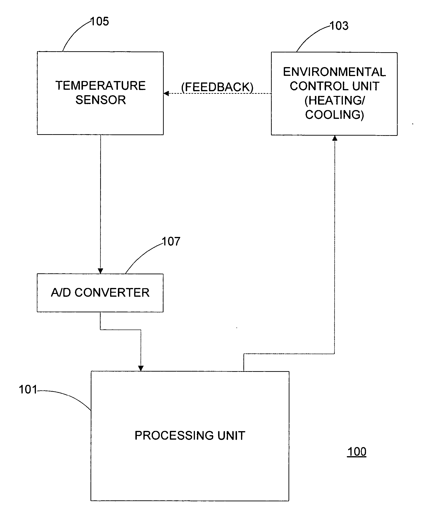
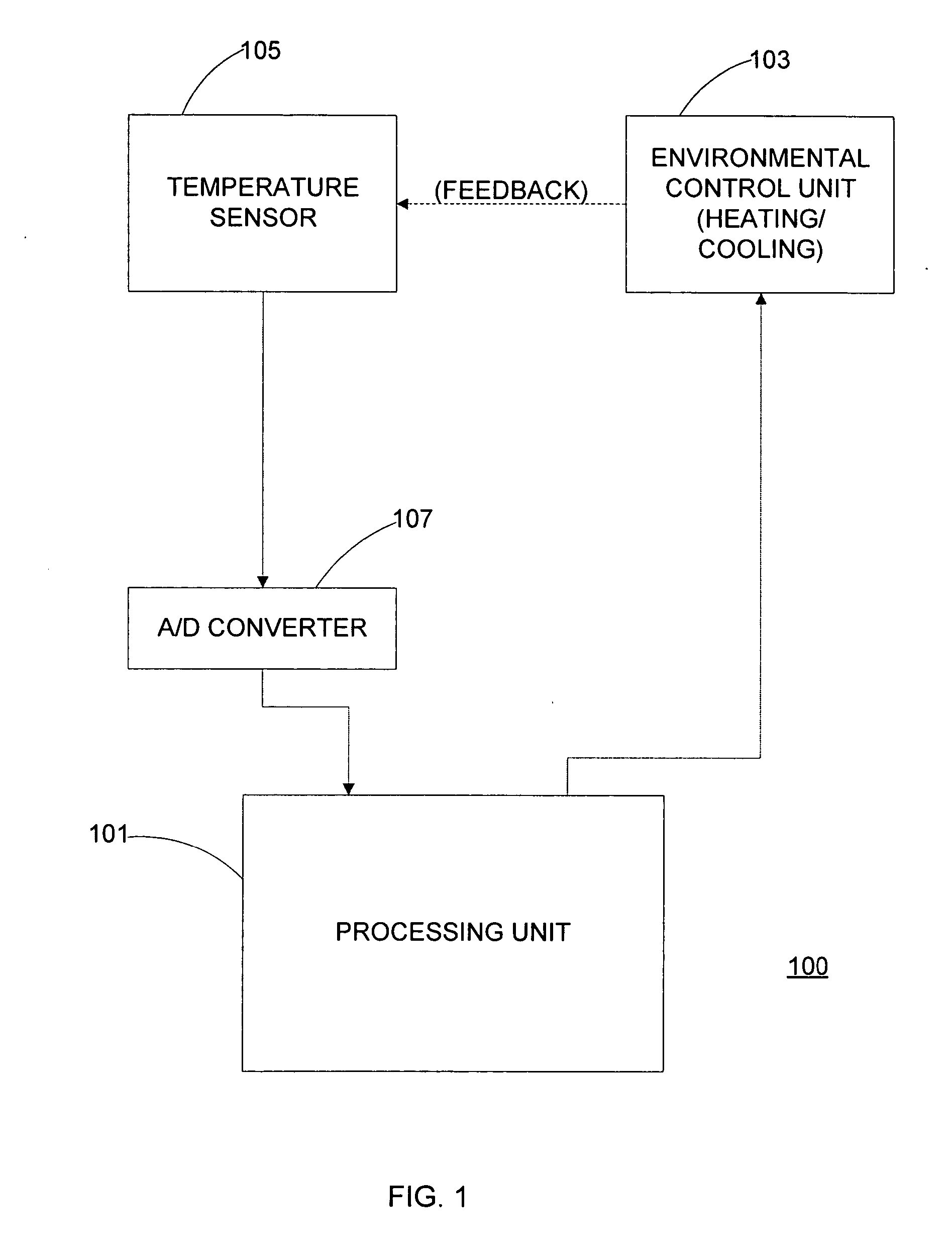
[0025]FIG. 1 shows an architecture of an apparatus 100 for controlling a temperature of a room in accordance with an embodiment of the invention. Apparatus comprises processing unit 101, environmental control unit 103, temperature sensor 105, and A / D (analog to digital) converter 107. In the embodiment, processing unit 101 comprises a microprocessor control unit (MCU) that includes a processor and memory that stores computer-executable instructions and data. Environmental control unit 103 may include a furnace to heat the room and / or an air conditioner to cool the room. The embodiment of the invention also supports a heat pump, which provides the functionality of both a furnace and an air conditioner. The embodiment shown in FIG. 1 may support a heating unit and / or a cooling unit. Typically, the cycle rate is also subject to other factors such as short cycle protection delay and start up delay as will discussed with FIGS. 10-19.

[0...


PUM


Abstract

The present invention controls a room temperature by controlling an environmental control unit. A total span about a setpoint temperature is adjusted in accordance with a previous total span and a multiplicative factor. The multiplicative factor is periodically updated from a desired cycle time and a previous cycle time. The room temperature may also be controlled by adjusting a duty cycle for controlling an environmental control unit. The duty cycle is adjusted based on an error associated with a previous control cycle and an attenuation factor. A new control cycle may be started by cutting the previous control cycle or a current control cycle may be extended if a predetermined condition is detected. The control mode is selected based on environmental characteristics and room characteristics. The control mode may include a span control mode and a duty cycle control mode that is selected from the cycle rate.

Description

FIELD OF THE INVENTION [0001] The present invention relates generally to the field of controlling room temperature by either heating or cooling a room. BACKGROUND OF THE INVENTION [0002] With the increased price of fuel and electricity, efficient temperature control of buildings is increasingly important. Room temperature control typically utilizes a “temperature span” method, in which a temperature range is specified between a setpoint temperature plus a fixed span temperature and the setpoint temperature minus the fixed span temperature. When heating a room, a heating unit turns off when the room temperature is higher than the setpoint temperature plus span temperature and turns on when room temperature is lower than the setpoint temperature minus span temperature. Similarly, when cooling the room, a cooling unit turns off when the room temperature is lower than the setpoint temperature minus span temperature and turns on when the room temperature is higher than the setpoint tempe...

Claims


Application Information

Patent Timeline
Patent Type & Authority Applications(United States)
IPC IPC(8): G05D23/00
CPCF24F11/0012G05D23/1917F24F2011/0064F24F11/006F24F11/30F24F2110/10F24F11/62F24F11/65F24F11/61F24F11/46
Inventor CHENG, CHUNG MING
Owner COMPUTIME LIMITED
Why Eureka
Try Eureka