Running support system for vehicle
a support system and vehicle technology, applied in the direction of reradiation, pedestrian/occupant safety arrangement, instruments, etc., can solve the problem of insufficient study of the appropriate control method for support control, and achieve the effect of convenient operation for the driver
- Summary
- Abstract
- Description
- Claims
- Application Information
AI Technical Summary
Benefits of technology
Problems solved by technology
Method used
Image
Examples
first embodiment
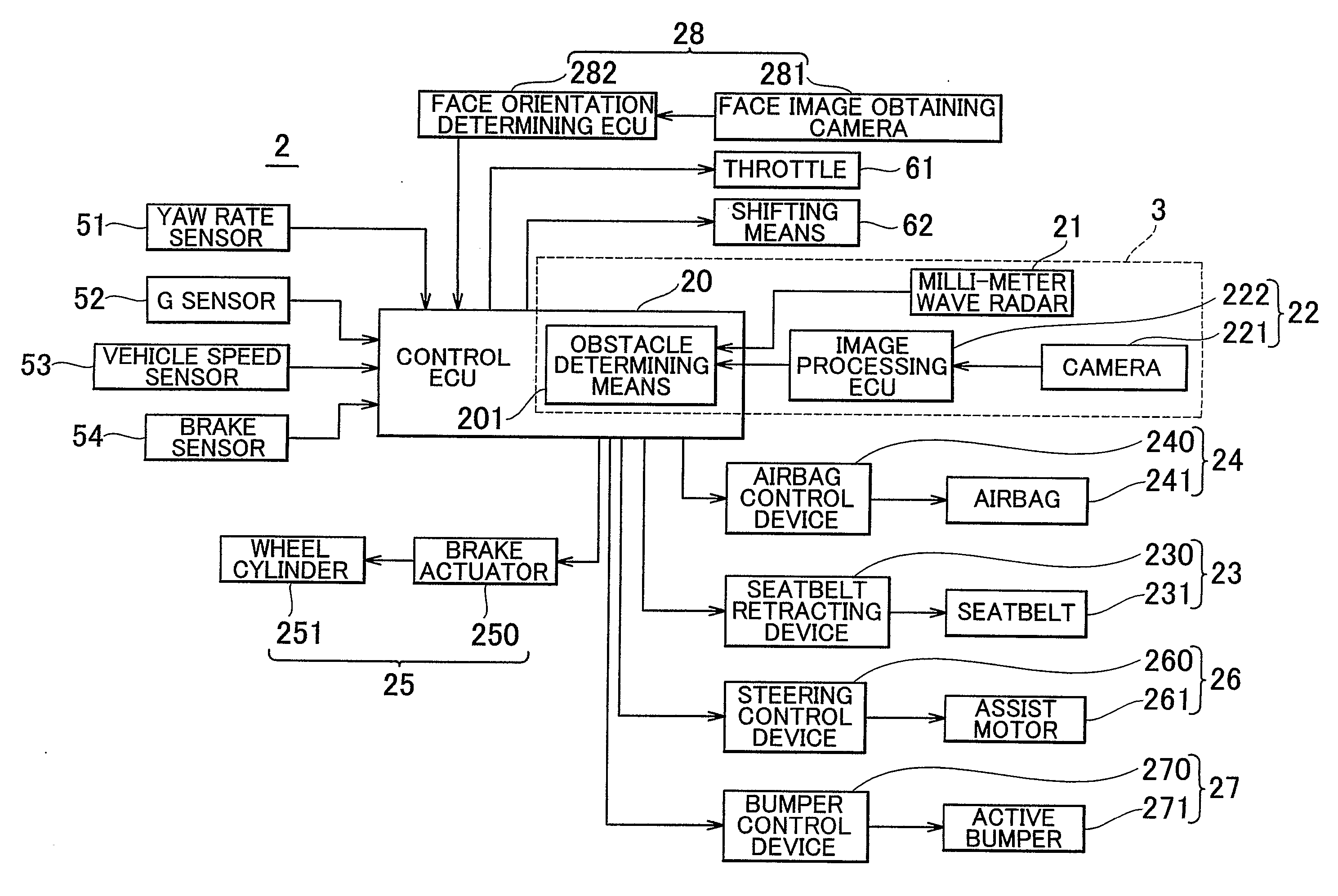
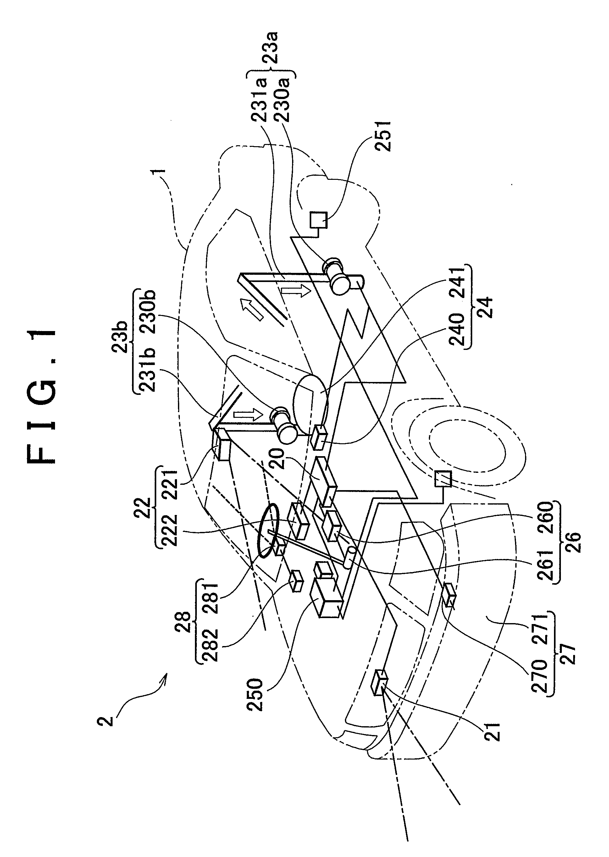
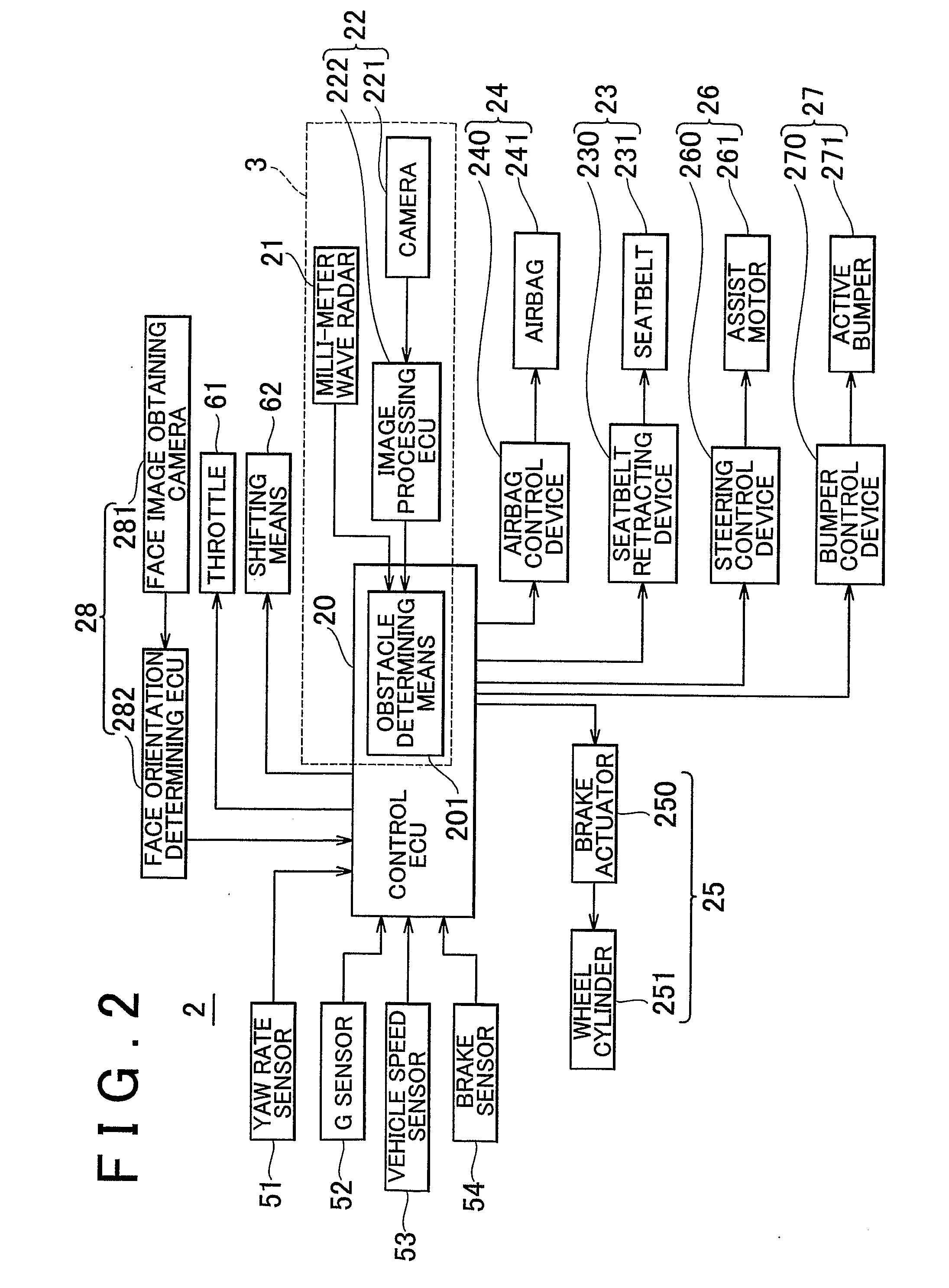
[0037]FIG. 1 is a view schematically showing a structure of a vehicle in which a running support system for a vehicle according to the invention is mounted. FIG. 2 is a block diagram showing a vehicle control system 2 corresponding to the running support system for a vehicle. The vehicle control system 2 mounted in a vehicle 1 includes an ECU 20 which controls the entire system; a millimeter wave radar 21 which corresponds to first object detecting means for scanning an area ahead of the vehicle and detecting an obstacle; image recognition means 22 corresponding to second object detecting means for obtaining an image of the area ahead of the vehicle and detecting an obstacle by performing image recognition; a seatbelt device 23, an airbag device 24, a brake device 25, an automatic steering device 26, a pedestrian protection device 27, each of the devices 23 to 27 corresponding to danger reducing means for reducing danger due to a collision; and a face orientation detecting device 28...
second embodiment
[0076] Next, a running support system for a vehicle according to the invention will be described with reference to FIGS. 4 and 5. FIG. 4 is a block diagram showing a vehicle control system 2a according to the embodiment. The basic structure of the vehicle control system 2a is the same as that of the vehicle control system 2 shown in FIG. 2, except for the fact that the vehicle control system 2a does not include the face orientation detecting device 28.
[0077] An obstacle determination according to the embodiment and a control operation based on the determination will be described with reference to the flowchart in FIG. 5. The control routine is repeatedly performed at predetermined intervals by the ECU 20 during the time period from when the power supply of the vehicle is turned ON until when the power supply is turned OFF.
[0078] First, a result of detection of a potential obstacle performed by the millimeter wave radar 21 is read in step S51, and a result of detection of a potentia...
PUM
 Abstract
Description
Claims
Application Information
 - R&D
- Intellectual Property
- Life Sciences
- Materials
- Tech Scout
- Unparalleled Data Quality
- Higher Quality Content
- 60% Fewer Hallucinations
Browse by: Latest US Patents, China's latest patents, Technical Efficacy Thesaurus, Application Domain, Technology Topic, Popular Technical Reports.
© 2025 PatSnap. All rights reserved.Legal|Privacy policy|Modern Slavery Act Transparency Statement|Sitemap|About US| Contact US: help@patsnap.com


