
Firmware loading device

Inactive Publication Date: 2007-07-19
INVENTEC CORP
View PDF2 Cites 3 Cited by
  • Summary
  • Abstract
  • Description
  • Claims
  • Application Information

AI Technical Summary

Benefits of technology

[0005] In light of the above prior-art drawbacks, a primary objective of the present invention is to provide a firmware loading device, by which a firmware with a correct edition can be automatically loaded into a data processing device without a complex process.
[0006] Another objective of the present invention is to provide a firmware loading device, by which human resources can be saved and time requirement can be reduced.
[0007] A further objective of the present invention is to provide a firmware loading device, by which the drawback that an operation failure of a data processing device is resulted as a firmware is wrongly loaded due to human errors can be eliminated.

Problems solved by technology

Thus, such complicated manual operation not only consumes human resources but also requires a huge amount of time.
Further, the firmware may be wrongly loaded due to human errors, such that an operation failure of the data processing device can be resulted.
When the firmware is wrongly loaded, the subsequent testing process and shipment cannot be successfully performed, so as to seriously affect the overall operation flow.

Method used


Image

  • Firmware loading device
  • Firmware loading device
  • Firmware loading device

Examples


Embodiment Construction

[0015] The present invention is described in the following with specific embodiments, so that one skilled in the pertinent art can easily understand other advantages and effects of the present invention from the disclosure of the invention. The present invention may also be implemented and applied according to other embodiments, and the details may be modified based on different views and applications without departing from the spirit of the invention.

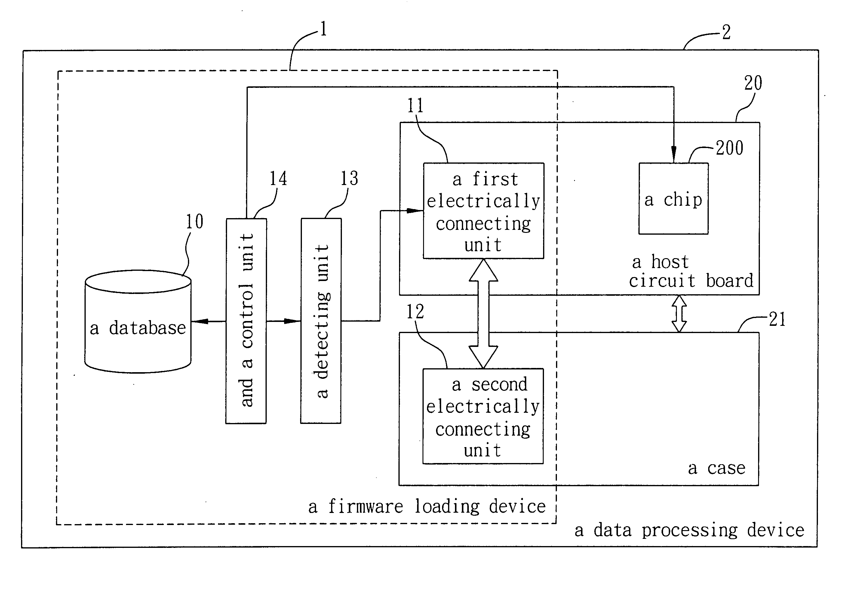
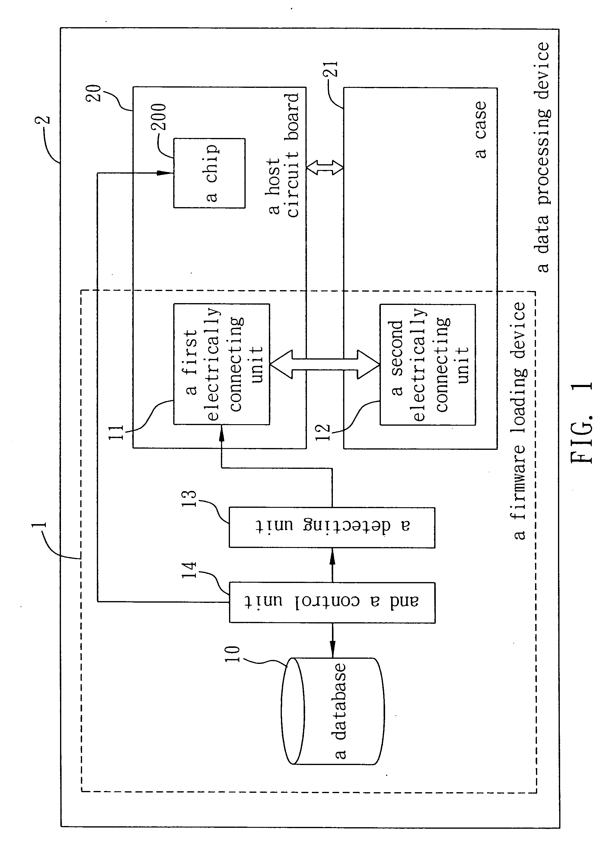
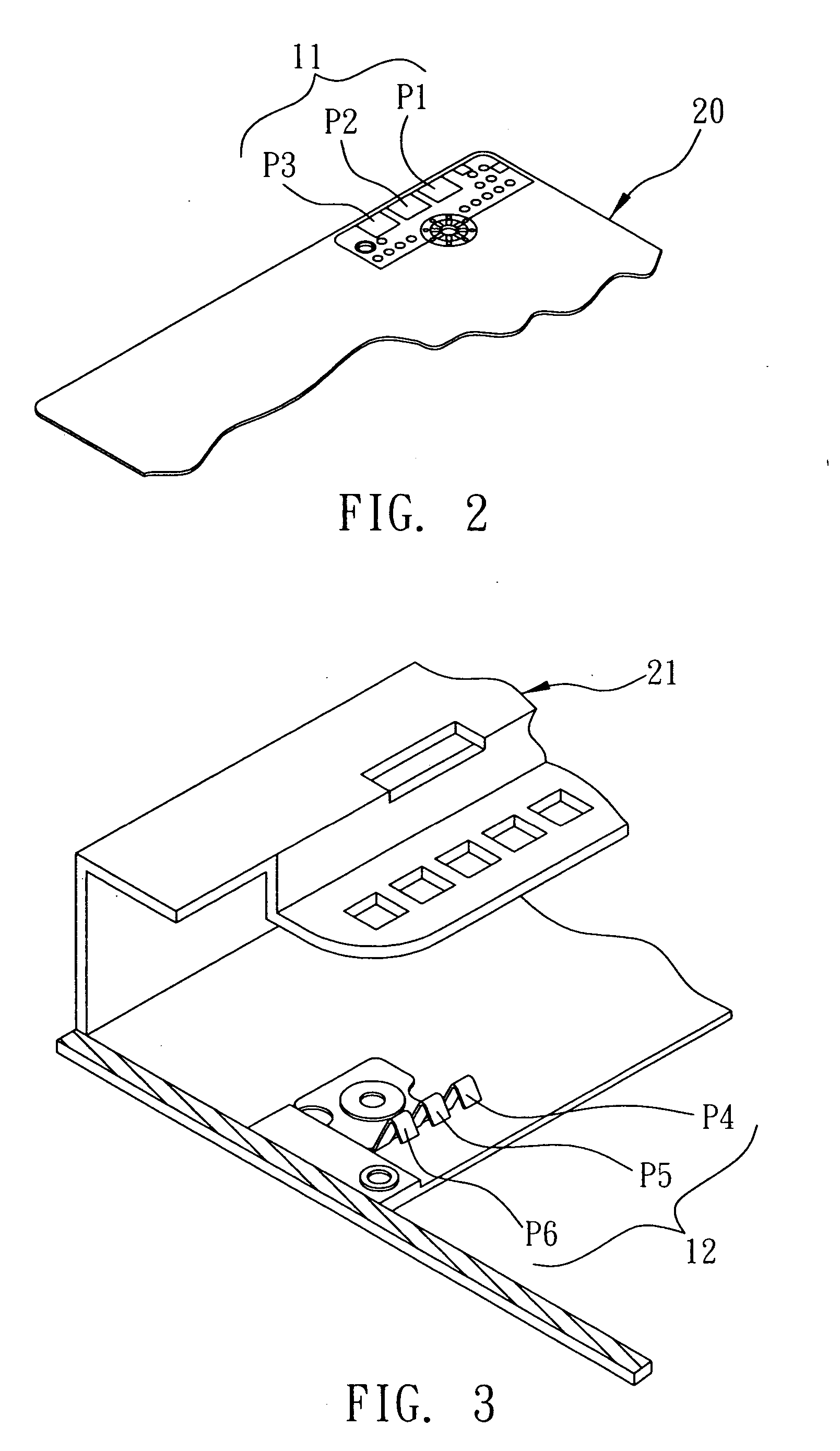
[0016]FIG. 1, FIG. 2 and FIG. 3 are relevant diagrams showing a firmware loading device according to a preferred embodiment of the present invention. These diagrams will serve to provide description for the firmware loading device proposed in the present invention. What needs to be concerned is that these drawings are simplified schematic diagrams, and thus only structures relevant to the present invention are illustrated. Also, these structures are not drawn according to actual amounts, shapes and dimensions. Actually, the amount, sh...


PUM


Abstract

A firmware loading device applied to a data processing device having a host circuit board and a case for receiving the host circuit board is proposed. A plurality of firmwares corresponding to the type of the case are stored in a database. A first electrically connecting unit and a corresponding second electrically connecting unit are respectively provided on the host circuit board and the case. A detecting unit serves to detect an electrical connection relationship between the first electrically connecting unit and the second electrically connecting unit after the host circuit board is assembled in the case. A control unit serves for fetch a firmware appropriate to the case from the database and load the firmware into the host circuit board according to the electrical connection relationship between the first and second electrically connecting units detected by the detecting unit.

Description

FIELD OF THE INVENTION [0001] The present invention relates to a firmware loading device, and more particularly, to a firmware loading device applied to a data processing device having a host circuit board and a case for receiving the host circuit board. BACKGROUND OF THE INVENTION [0002] A firmware is a program embedded in a programmable hardware device, for example, a basic input and output system (BIOS) program. A firmware device is able to use a software tool to write data of a newly edited basic input and output system (BIOS) program into a computer. Further, a firmware device can also update different speeds for a flash memory of a modem. When the device is turned on, a power on self test (POST) is run. For example, the communication between the device itself and other devices and the operation of the device can be tested. [0003] Referring to the firmware which is loaded into a current data processing device, the appropriate firmware is correspondingly loaded only after the as...

Claims


Application Information

Patent Timeline
IPC IPC(8): G06F9/445
CPCG06F8/60
Inventor HSU, YUNG-CHINHSIEH, CHI-KANGCHANG, LIN-WEI
Owner INVENTEC CORP
Learn More