Rotating shaft structure with automatic locking mechanism

a technology of automatic locking and rotating shaft, which is applied in the direction of wing accessories, instruments, portable computers, etc., can solve the problems of increasing assembly complexity, manufacturing cost, and requiring a limit on the movement angle of a good rotating shaft, so as to achieve the effect of limiting the angle movemen

Active Publication Date: 2007-07-26
HO CHI JUNG +2
View PDF12 Cites 57 Cited by
  • Summary
  • Abstract
  • Description
  • Claims
  • Application Information

AI Technical Summary

Benefits of technology

[0010] Still yet another object of the present invention is to provide a rotating shaft structure with automatic locking mechanism, wherein a stop block is provided around the core hole of the main frame adjacent to the axial member and a stop part is socketingly connected and linking-up with the shaft such that the radially protruding double stop edge contacts against the stop block to limit the angle movement.

Problems solved by technology

In fact, the design for a good rotating shaft requires a limit on movement angle as well as a necessary arresting effect.
However, for this type of automatic locking mechanism, the rotating shaft structure with automatic locking mechanism has to be provided with corresponding holes and locking elements, leading to an increase in the complexity for assembly and the manufacturing cost.

Method used


Image

  • Rotating shaft structure with automatic locking mechanism
  • Rotating shaft structure with automatic locking mechanism
  • Rotating shaft structure with automatic locking mechanism

Examples


Embodiment Construction

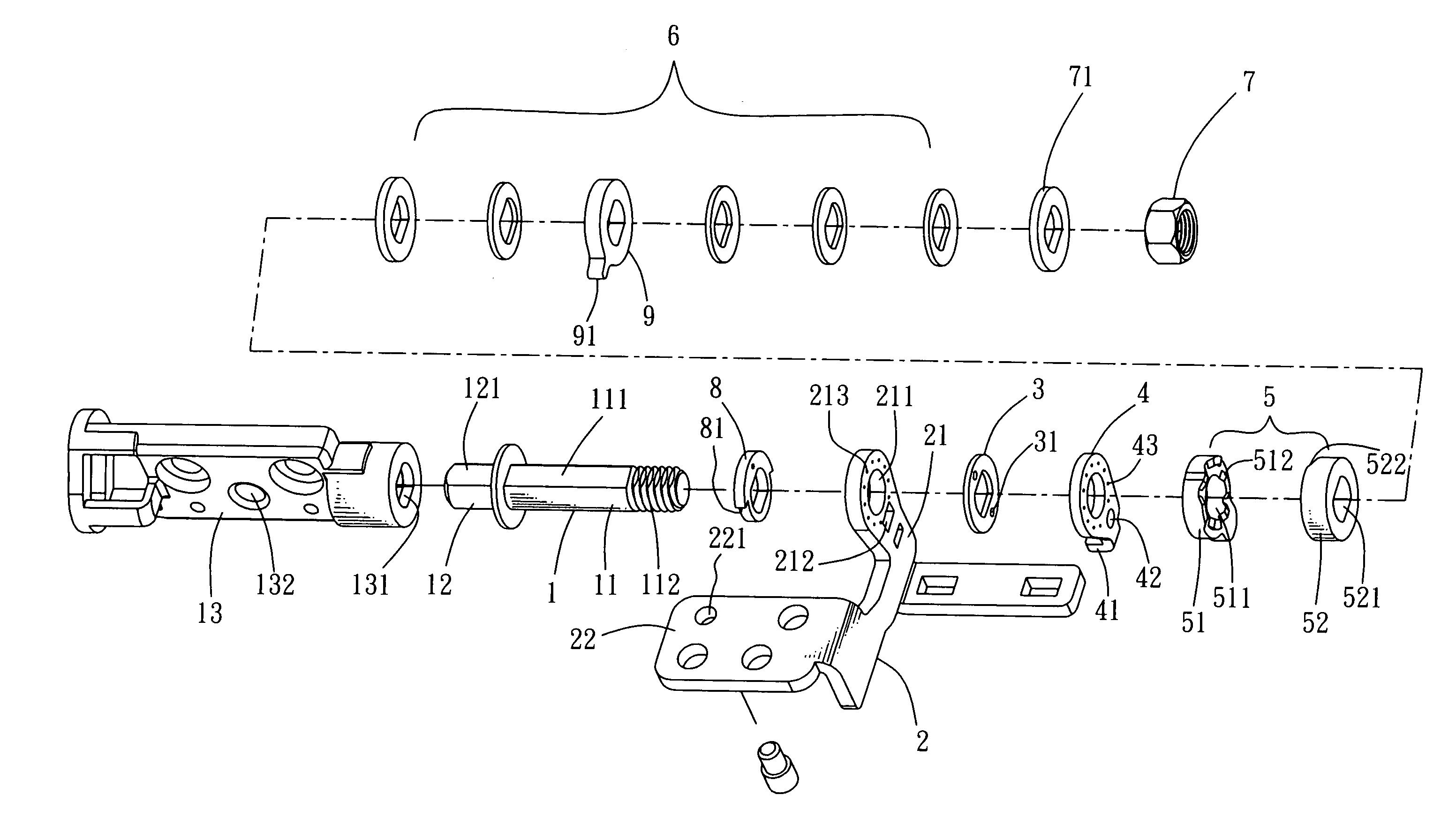
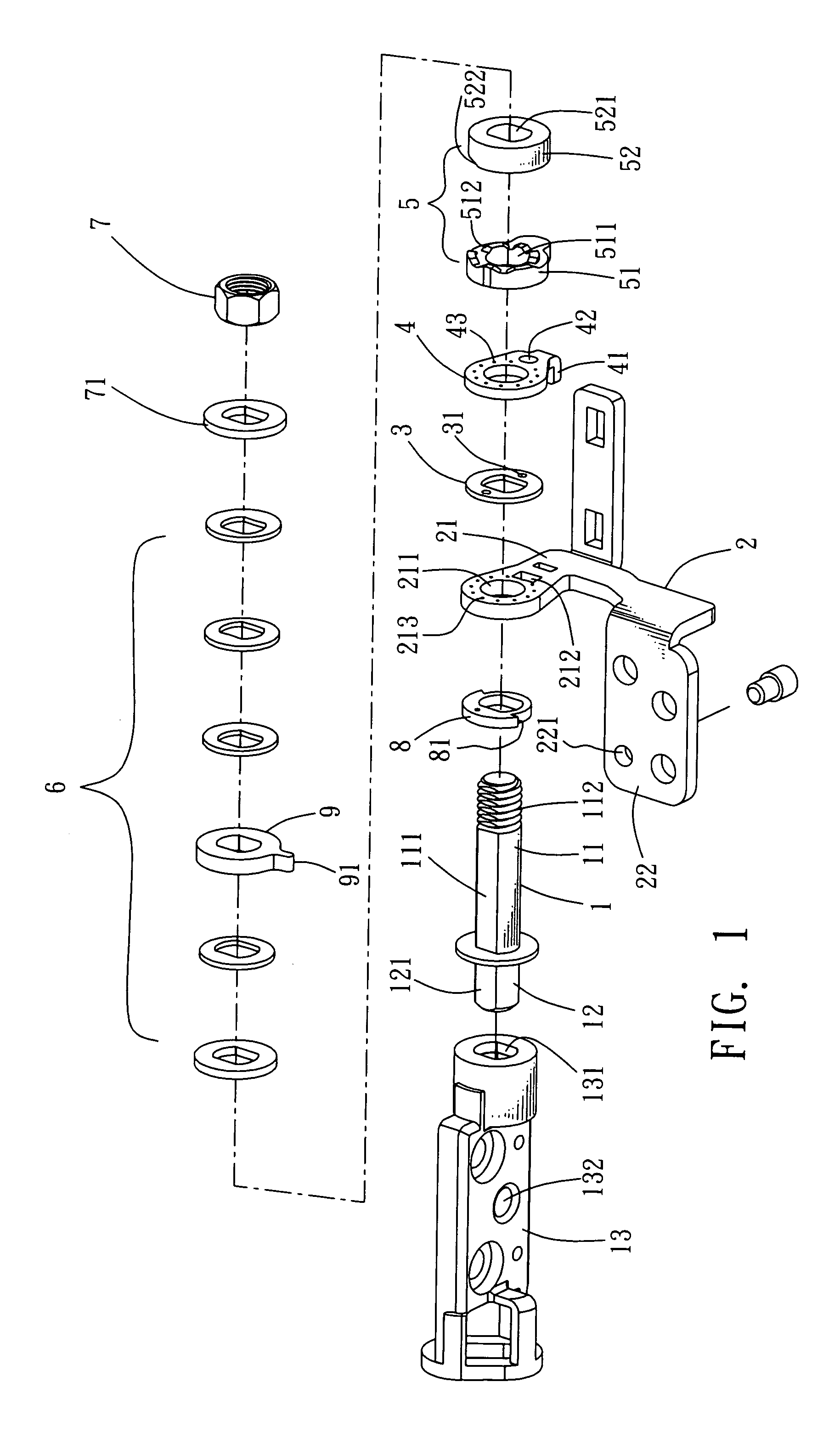
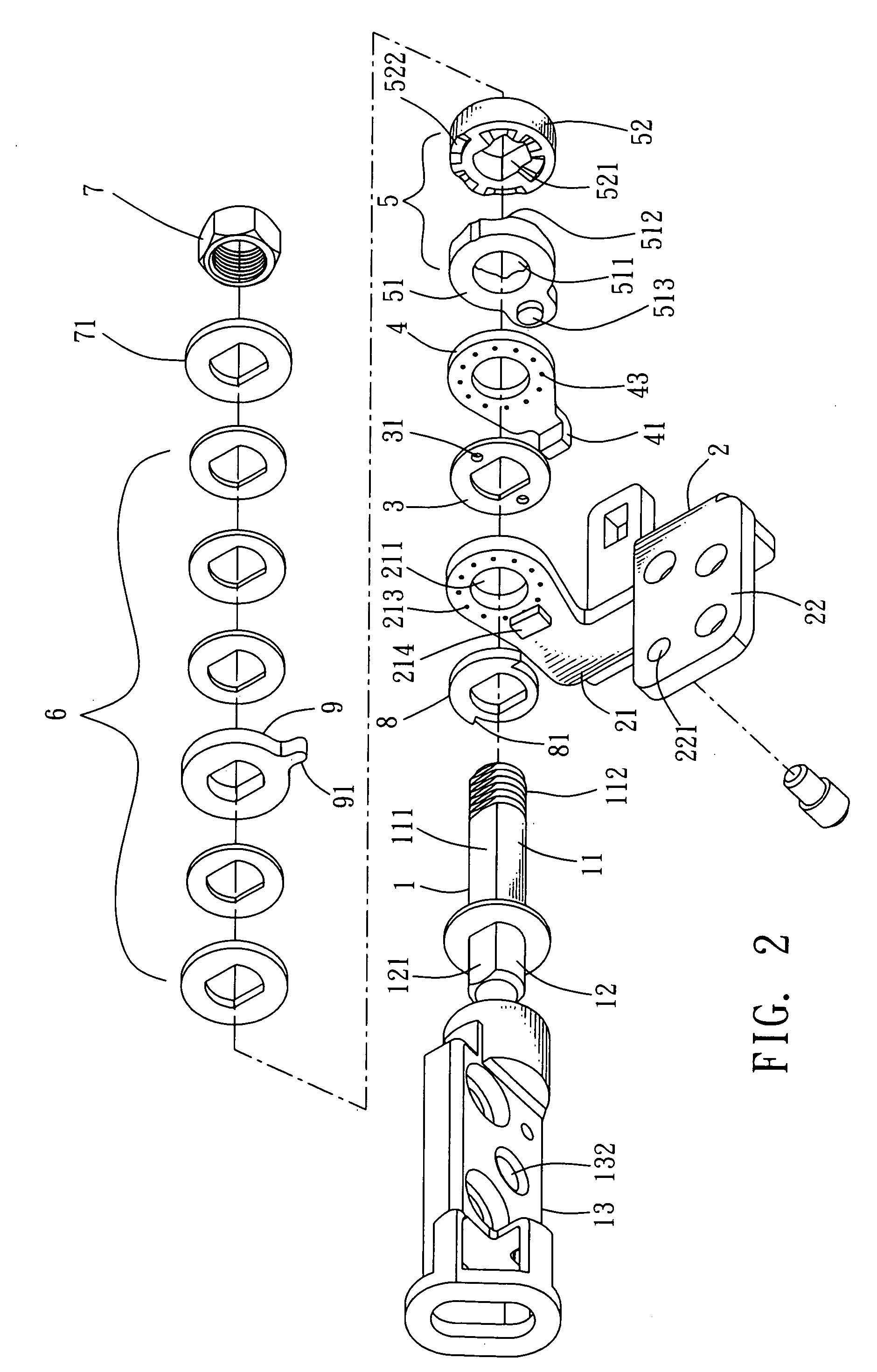
[0019] Referring to FIGS. 1 to 5, a rotating shaft structure according to the present invention comprises an axial member 1, a main frame 2, a friction disc 3, a connecting part 4, a cam member 5, at least an elastic body 6, and an end enclosure 7.

[0020] The axial member 1 is a rod comprising a shaft 11 and a linking portion 12. The shaft 11 comprises at least a milling plane 111 to be socketingly connected with the friction disc 3 and the sliding part 52 of the cam member 5 so as to move simultaneously with the shaft 11. Furthermore, the shaft 11 extends from its free end to form a connecting segment 112 to be connected with the end enclosure 7 described later so as to prevent the elements described later from coming off axially.

[0021] The linking portion 12 is connected with an object, a cover for example, as shown in the figures. The linking portion 12 includes a connecting rid 121 provided with a milling plane so as to be insertingly engaged with the cover. However, the connec...


PUM


Abstract

The present invention discloses a rotating shaft structure with automatic locking mechanism, characterized in which a shaft extending axially from an axial member passes through, in sequence, the core hole of the upright frame plane of the main frame, a friction disc, a disc-like connecting part connected with the frame plane, a cam member comprising a fastening part and a sliding part, at least an elastic body, and a connecting segment on the free end of the shaft connected with a end enclosure so as to form axial pressure to constrain the elements described above. The shaft and the main frame are provided with a linking portion and a connecting portion, respectively. The outer and inner edges of the adjoining planes between the fastening part and the sliding part are provided with at least a wedge block and at least a wedge slot alternately so as to connect the fastening part and the sliding part together. Consequently, when the axial member rotates, the inclined plane of the wedge slot of the sliding part moves upward along the inclined plane of the wedge block and thus axially presses the elastic body so as to prompt the contact plane of the sliding part to rotate along the wedge blocks of the fastening part. When the axial member rotates reversely, the wedge slots of the sliding part move to the wedge blocks of the fastening part and, under the extending action of the elastic body, the wedge slots are engaged into the wedge blocks so as to form an automatic locking of butting joint.

Description

FIELD OF THE INVENTION [0001] The present invention relates to a rotating shaft structure, and particularly to a rotating shaft structure with automatic locking mechanism, in which a friction disc arranged between the main frame and the connecting part to significantly increase the service life of the rotating shaft structure. BACKGROUND OF THE INVENTION [0002] Consumer electronics with flip covers, such as portable computer, electronic dictionary, portable audio / video player, flip mobile phone, generally has a main body on the bottom, which is pivotally connected with the cover on the top, such that the cover may swing open or close with respect to the main body. Consequently, the rotating shaft is key to the quality of the products described above. In fact, the design for a good rotating shaft requires a limit on movement angle as well as a necessary arresting effect. [0003] To prevent the main body and the cover of the 3C electronic products described above from swinging open arb...

Claims


Application Information

Patent Timeline
Patent Type & Authority Applications(United States)
IPC IPC(8): E05D11/10
CPCE05D11/087E05Y2900/606G06F1/1616Y10T16/540345G06F1/1681H04M1/0216Y10T16/540255G06F1/1679
Inventor HO, CHI-JUNGPENG, CHIH-HUANG
Owner HO CHI JUNG
Why Eureka
Try Eureka