Radiator support structure

Active Publication Date: 2007-07-26
KUBOTA LTD
View PDF10 Cites 12 Cited by
  • Summary
  • Abstract
  • Description
  • Claims
  • Application Information

AI Technical Summary

Benefits of technology

[0009]Since the radiator is located between the support columns of the rollo

Problems solved by technology

Consequently, the motor section accommodating the radiator and engine tends to be long in the f

Method used


Image

  • Radiator support structure
  • Radiator support structure
  • Radiator support structure

Examples


Example

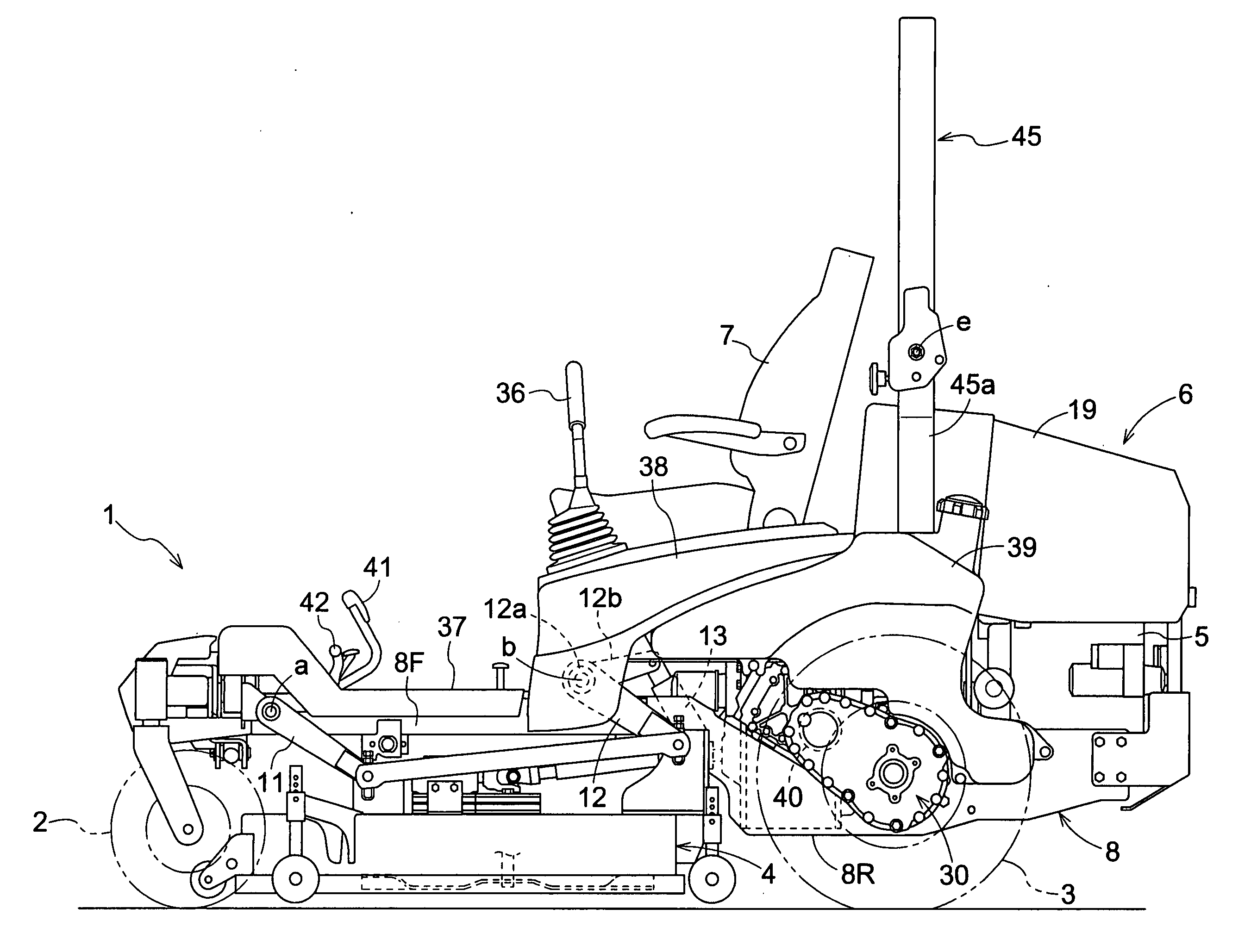
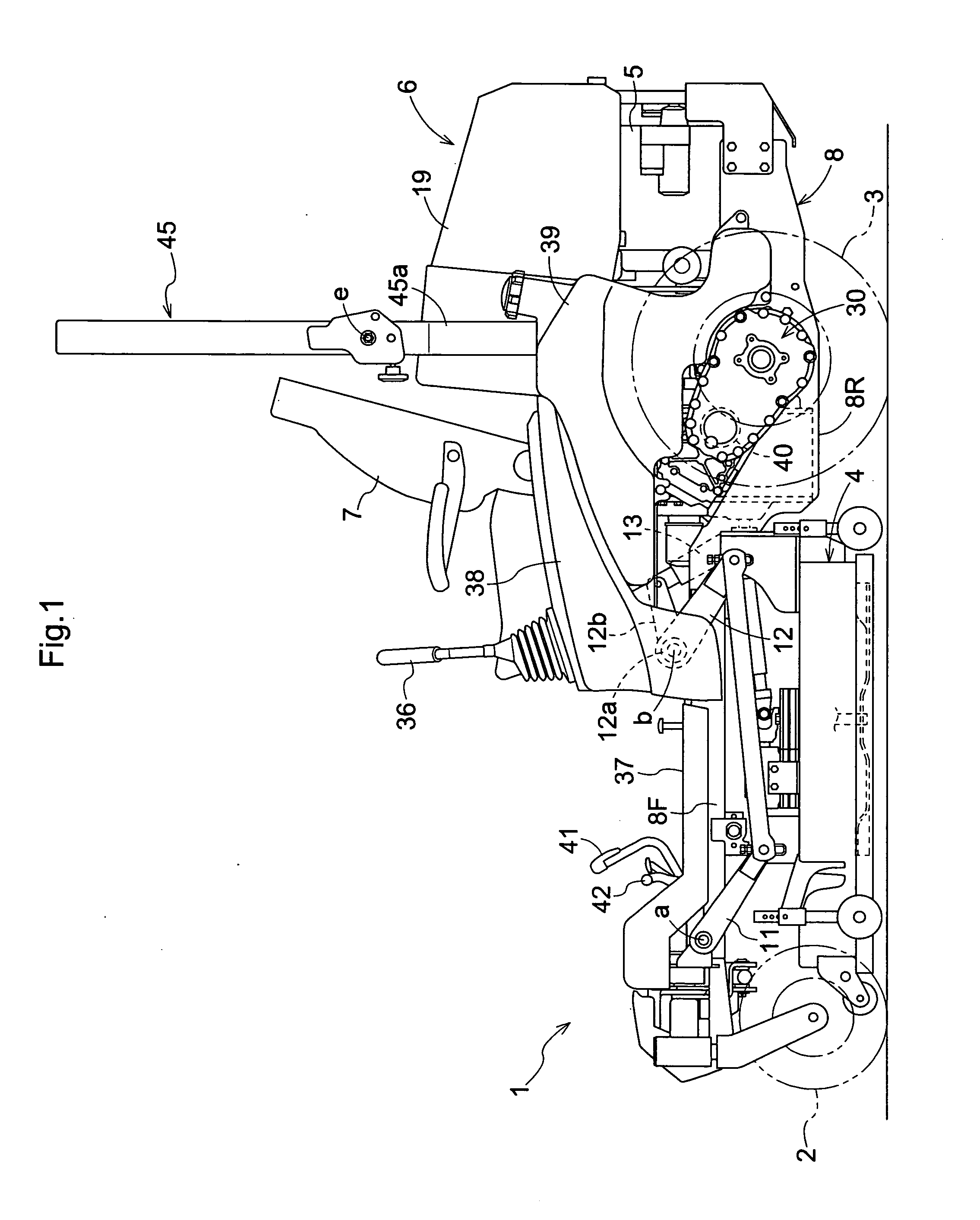
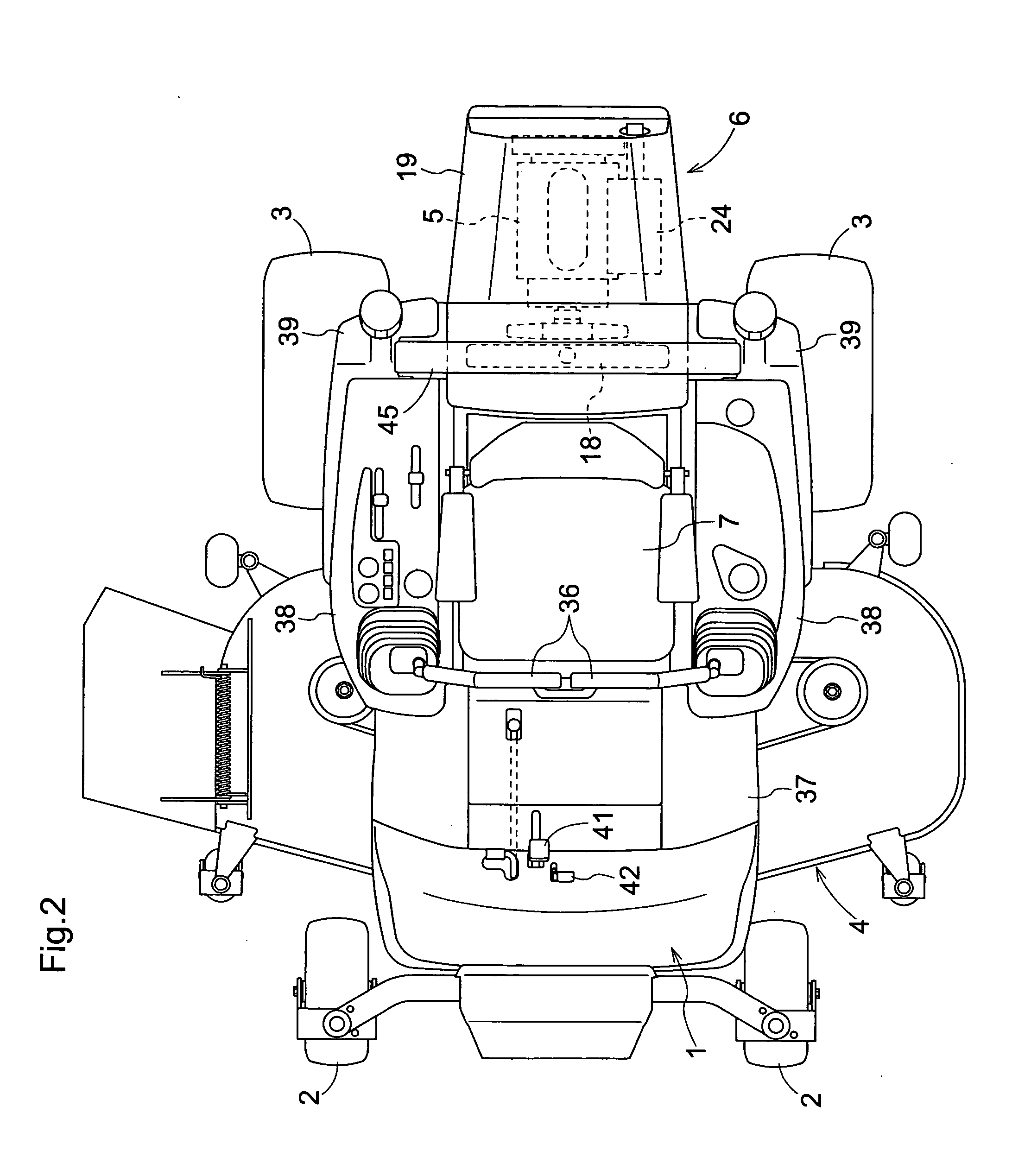
[0022]FIG. 1 shows a side elevation of a riding type mower according to this invention. FIG. 2 shows a plan view of the grass mower. This riding type mower is what is called a mid-mount mower with a bar blade type mower unit 4 suspended from a vehicle body 1 between a pair of right and left front wheels 2 and a pair of right and left rear wheels 3. The vehicle body 1 has a motor section 6 mounted on a rear portion thereof and housing an engine 5, and a driver's seat 7 disposed in an intermediate position in the fore and aft direction of the vehicle body 1.

[0023]The right and left front wheels 2 are in the form of caster type idle wheels. The right and left rear wheels 3 are drive wheels subjected to stepless speed changing and reversibly driven independently of each other. The mower can travel straight forward or backward by driving the right and left rear wheels 3 at equal speed forward or backward, and can turn to a selected direction by driving the right and left rear wheels 3 at...


PUM


Abstract

A riding type mower comprises: a plurality of wheels; a vehicle body supported by the plurality of wheels; a water-cooled engine located in a rear region of the vehicle body; a hood for covering the engine; a driver's seat located forwardly of the hood; a rollover protection frame located between the driver's seat and the water-cooled engine, the rollover protection frame having a pair of right and left support columns spaced apart from each other in a lateral direction; a radiator for the water-cooled engine located between the pair of the support columns of the rollover protection frame.

Description

BACKGROUND OF THE INVENTION[0001]This invention relates to a riding type mower having a rollover protection frame.[0002]A known riding type mower of the type noted above includes a motor section disposed at the rear of a vehicle body having front wheels and rear wheels, a driver's seat mounted forwardly of the motor section, and an arch-shaped rollover protection frame erected rearwardly of the driver's seat (see Japanese Unexamined Patent Publication No. 2004-237953, for example).[0003]In the above conventional riding type mower, an air-cooled gasoline engine is mounted in the motor section to make the motor section short in the fore and aft direction, thereby to make the vehicle body compact over the entire length thereof. However, a high-power water-cooled engine is desired in order to improve running capability and grass cutting capability.[0004]With the water-cooled engine, generally, a radiator cooled by a cooling fan driven by engine power is disposed in front of the engine. ...

Claims


Application Information

Patent Timeline
IPC IPC(8): A01D34/00
CPCA01D34/66B60K11/04B60Y2200/223
Inventor UMEMOTO, HIDEYAMINOURA, AKIRAFUJIWARA, OSAMINOGAMI, KAZUAKIKOMORIDA, TAKESHI
Owner KUBOTA LTD
Why Eureka
Try Eureka