Window shade cutting apparatus

Inactive Publication Date: 2007-07-26
TEH YOR CO LTD
View PDF35 Cites 4 Cited by
  • Summary
  • Abstract
  • Description
  • Claims
  • Application Information

AI Technical Summary

Benefits of technology

[0008] The present invention is an apparatus for cutting window shades and a method for operating the apparatus. Typically, such window shades comprise a head rail, a bottom rail, and one

Problems solved by technology

This approach is expensive as it lacks any economies of scale.
Custom orders also require substantial time to tool up and manufacture each particular window shade.
Providing linear blade movement adds to the complexity r

Method used


Image

  • Window shade cutting apparatus
  • Window shade cutting apparatus
  • Window shade cutting apparatus

Examples


Embodiment Construction

[0038] The invention disclosed herein is susceptible to embodiment in many different forms. Shown in the drawings and described in detail hereinbelow is a preferred embodiment of the present invention. The present disclosure, however, is an exemplification of the principles and features of the invention, but does not limit the invention to the illustrated embodiments.

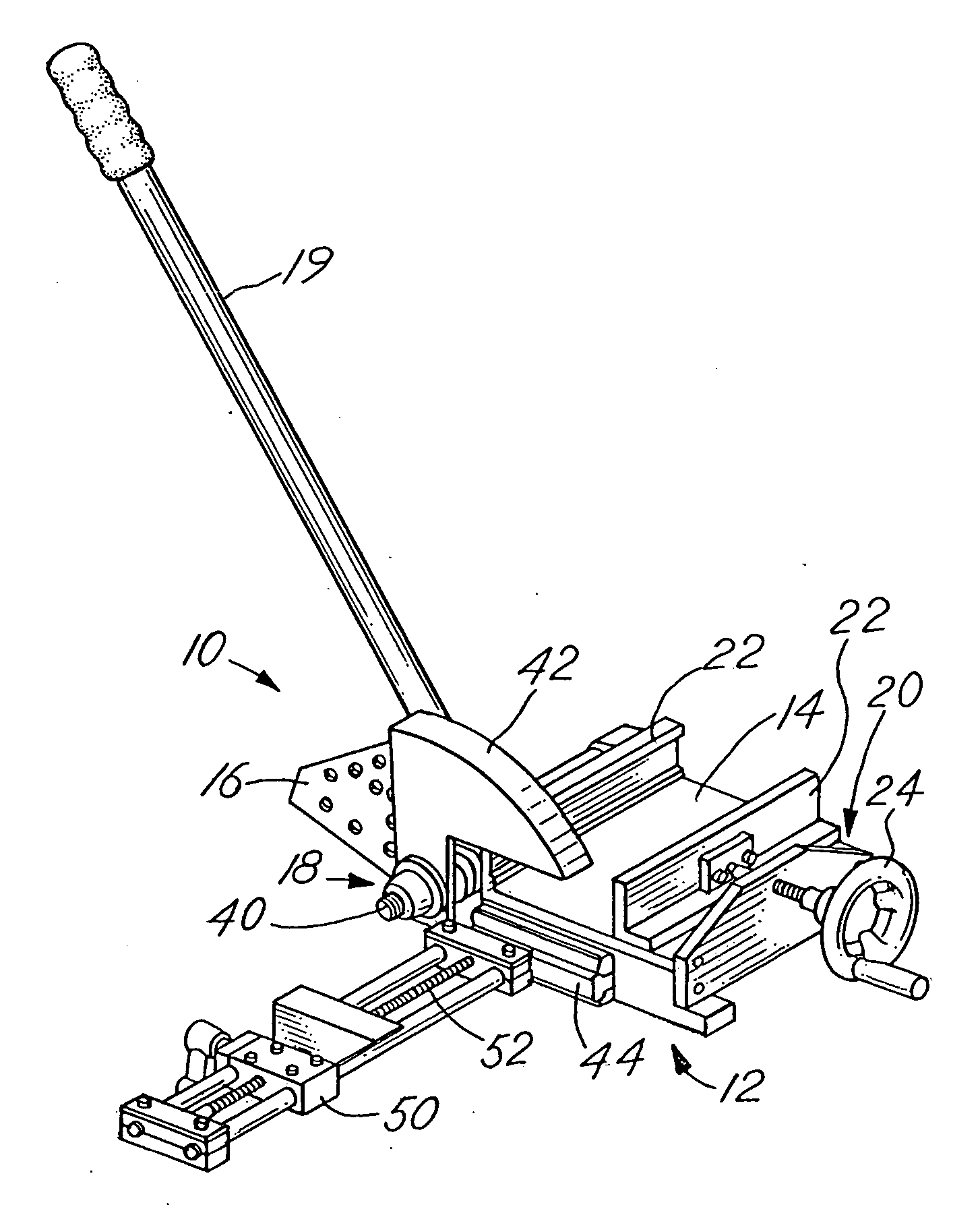
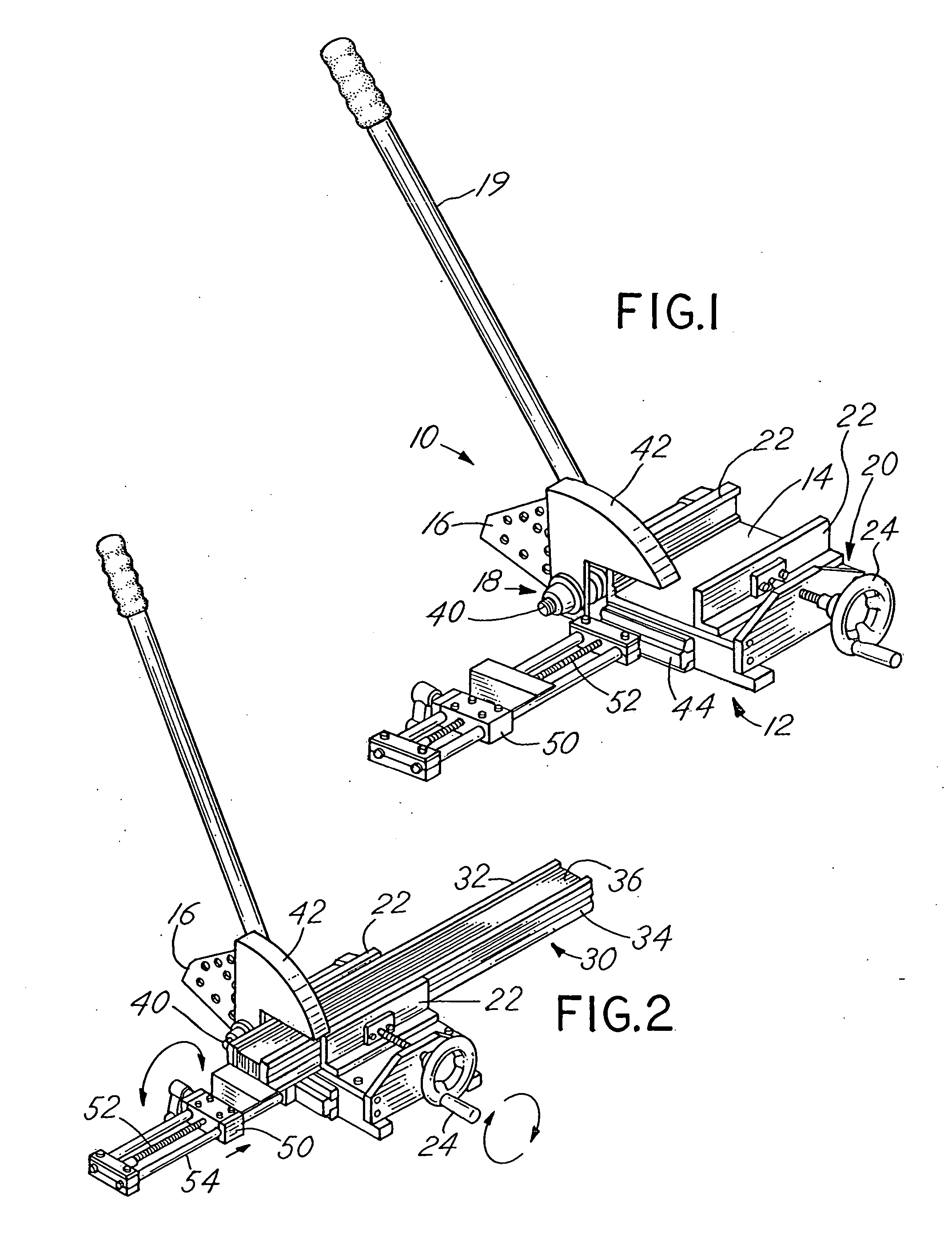
[0039] Referring to FIGS. 1 and 2, an embodiment of a window shade cutting apparatus 10 according to the present invention is shown. The apparatus 10 includes a body 12 comprising a platform 14 for supporting a window shade 30. Although shown as a planar member extending the width of the window shade 30, it should be understood that platform 14 can also take the form of vertical supports or other configurations suitable for supporting a window shade 30. The apparatus also includes blade 16 and an actuating mechanism 18 that is operated by lever arm 19. The apparatus 10 further comprises a clamp mechanism 20 including o...


PUM

PropertyMeasurementUnit
Pressureaaaaaaaaaa

Abstract

A cutting machine for window shades comprising a head rail, a bottom rail, and a plurality of light blocking sections. The cutting machine comprises a body with a platform for supporting the window shade, a clamp mechanism for securing the window shade, a blade rotationally connected to the body for cutting the window shade, and an actuating mechanism. The actuating mechanism is operatively connected to the blade, causing the blade to move in a rotational movement for cutting the secured window shade.

Description

RELATED APPLICATIONS [0001] This application is a continuation-in-part of U.S. patent application Ser. No. 11 / 338,465 filed on Jan. 24, 2005.FIELD OF INVENTION [0002] This invention relates to a cutting apparatus for a window shade and a method for using the apparatus. In particular, this invention relates to a cutting apparatus that can cut the ends of the components of a typical window shade, namely, the head rail, bottom rail and light blocking sections with a blade that travels an arcuate path in one action. BACKGROUND OF INVENTION [0003] Window shades are a well known covering for windows and typically include a head rail, a bottom rail and a plurality of light blocking sections. The head rail and bottom rail are typically made of a relatively strong and rigid material. Each window shade component is designed to extend horizontally across the window space. [0004] Window frames are built in a myriad of different widths. In order to accommodate this variation in widths, window sh...

Claims


Application Information

Patent Timeline
IPC IPC(8): B26D7/02B26D5/08
CPCB26D7/02B23D23/00Y10T83/8821Y10T83/7487Y10T83/9447Y10T83/75
Inventor YU, FU-LAIHUANG, CHIN-TIEN
Owner TEH YOR CO LTD
Why Eureka
Try Eureka