Chamber for reaction of lithium and deuterium

a chamber and lithium-deuterium technology, applied in the field of electrochemical devices, can solve the problems that the aqueous electrolyte is not the only appropriate solution, and achieve the effect of facilitating interactions

Inactive Publication Date: 2007-07-26
SCHLAIKJER CARL R
View PDF4 Cites 4 Cited by
  • Summary
  • Abstract
  • Description
  • Claims
  • Application Information

AI Technical Summary

Benefits of technology

[0011] The purpose of this invention is principally to provide a better means for facilitating interactions occurring in systems which contain the materials discussed above. The objective is to bring both deuterium and lithium into a metallic matrix at the same time.

Problems solved by technology

Yet an aqueous electrolyte seems hardly the only appropriate one to choose to admit lithium into the metallic matrix, since as already stated, metallic lithium reacts with water.

Method used


Image

  • Chamber for reaction of lithium and deuterium
  • Chamber for reaction of lithium and deuterium

Examples


Embodiment Construction

[0018] A description of preferred embodiments of the invention follows.

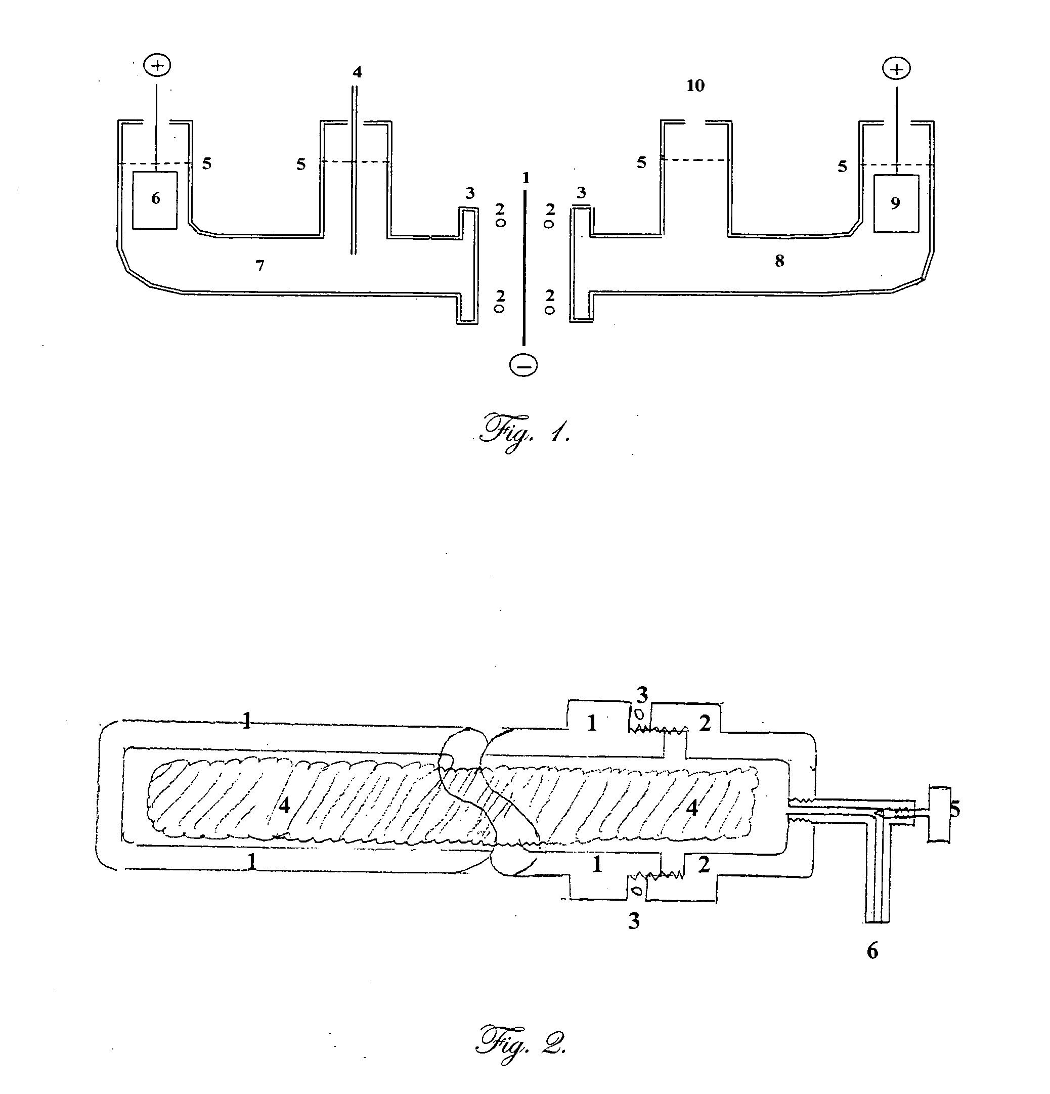
[0019]FIG. 1 is a cross section of an electrochemical cell according to one embodiment of this invention. The body is constructed from cylindrical borosilicate glass tubes, such as Pyrex™. Element number 1 is a flat membrane, for example palladium foil, in which the hydrogen (deuterium) and the lithium are to be brought together. It is the common cathode, or the negative electrode where electrochemical reduction occurs. This electrode is connected to the negative terminal of each of the two direct current power supplies. The power supplies regulate the current through each half of the cell.

[0020] Element number 2 shows the position of the O ring seals which fit within flanges, 3, on each half of the cell. Not shown is the clamp needed to compress the flanges against the O rings and the common cathode, 1.

[0021] During electrolysis in the aqueous (left) side, some, but not all of the hydrogen (deuterium) will be...


PUM

PropertyMeasurementUnit
boiling pointaaaaaaaaaa
metallicaaaaaaaaaa
heat resistantaaaaaaaaaa

Abstract

An electrochemical device is described which consists of two electrolyte chambers separated by a common electronically conducting cathode, such as a metal foil. On one side of the common cathode is a non-aqueous electrolyte which does not react with lithium metal and from which lithium metal may be plated. On the other side of the common cathode is an aqueous electrolyte from which isotopes of hydrogen may be electrochemically reduced on the common cathode. The cathode is impervious to either electrolyte. The anode on the non-aqueous side contains lithium metal, and on the aqueous side, the anode is an electronically conductive material which will not react with the electrolyte during the electrochemical release of oxygen. The purpose of the common cathode is to bring elemental lithium and elemental hydrogen together by diffusion within a metallic matrix, free of either electrolyte. Additionally, a non-electrochemical device is described which allows isotopes of lithium and hydrogen to interact within an alloy capable of absorbing both elements in a condensed phase.

Description

RELATED APPLICATION [0001] This application claims the benefit of U.S. Provisional Application No. 60 / 754,576, filed on Dec. 27, 2005. The entire teachings of the above application is incorporated herein by reference.TECHNICAL FIELD [0002] This invention relates to electrochemical devices, and particularly devices intended to separate elements from electrolytic solutions containing their compounds. Further, this invention relates to a novel method for bringing reactants together apart from the electrolyte from which they are obtained, in a way which can be controlled by regulating the current or pressure. BACKGROUND OF THE INVENTION [0003] One of the most serious problems facing society is our ever growing need for energy, and our almost complete dependence on non-renewable sources, including fossil fuels such as petroleum and coal, to fill this need. If renewable sources of energy could be used to offset some of our stationary needs, such as heating and electrical power, some of th...

Claims


Application Information

Patent Timeline
Patent Type & Authority Applications(United States)
IPC IPC(8): C25B9/00C25B11/04
CPCY02E30/18G21B3/00Y02E30/10
Inventor SCHLAIKJER, CARL R.
Owner SCHLAIKJER CARL R
Why Eureka
Try Eureka