Deionization and desalination using electrostatic ion pumping

a technology of electrostatic ion pumping and desalination, applied in the direction of fluid pressure measurement, liquid/fluent solid measurement, peptide, etc., can solve the problems of large pressure drop across the membrane, large energy consumption of reverse osmosis system, and membrane deformation, etc., to facilitate directed movement, increase the amount of water available, and reduce the cost of desalination and use.

Active Publication Date: 2007-07-26
RGT UNIV OF MINNESOTA +1
View PDF7 Cites 27 Cited by
  • Summary
  • Abstract
  • Description
  • Claims
  • Application Information

AI Technical Summary

Benefits of technology

[0012] Another aspect of the present invention is directed to a desalination apparatus that includes a feed flow channel; a concentrate flow channel; a plurality of flow channels configured to fluidly communicate an oscillating flow between the feed and the concentrate flow channels; and one or more pairs of conductive plates adapted about the plurality of flow channels, wherein an applied synchronized periodic electric field to the one or more pairs of conductive plates in conjunction with the oscillating flow facilitates a directed movement of predetermined ions therethrough the predetermined flow channels from the feed flow channel to the concentrate flow channel.
[0013] A final aspect of the present invention is directed to a capacitive deionization pumping system that includes: a feed flow channel; a concentrate flow channel; a plurality of flow channels configured to fluidly communicate an oscillating flow between the feed flow channels and the concentrate flow channels; and one or more pairs of conductive plates adapted about the plurality of flow channels, an electrical circuit electrically coupled to the one or more pairs of conductive plates; a fluid circuit fluidly coupled to the feed fl...

Problems solved by technology

Reverse osmosis systems require significant energy to move the water through the membrane.
The flux of water through the membrane results in a considerable pressure drop across the membrane.
This pressure drop is responsible for most of the energy consumption by t...

Method used


Image

  • Deionization and desalination using electrostatic ion pumping
  • Deionization and desalination using electrostatic ion pumping
  • Deionization and desalination using electrostatic ion pumping

Examples


Embodiment Construction

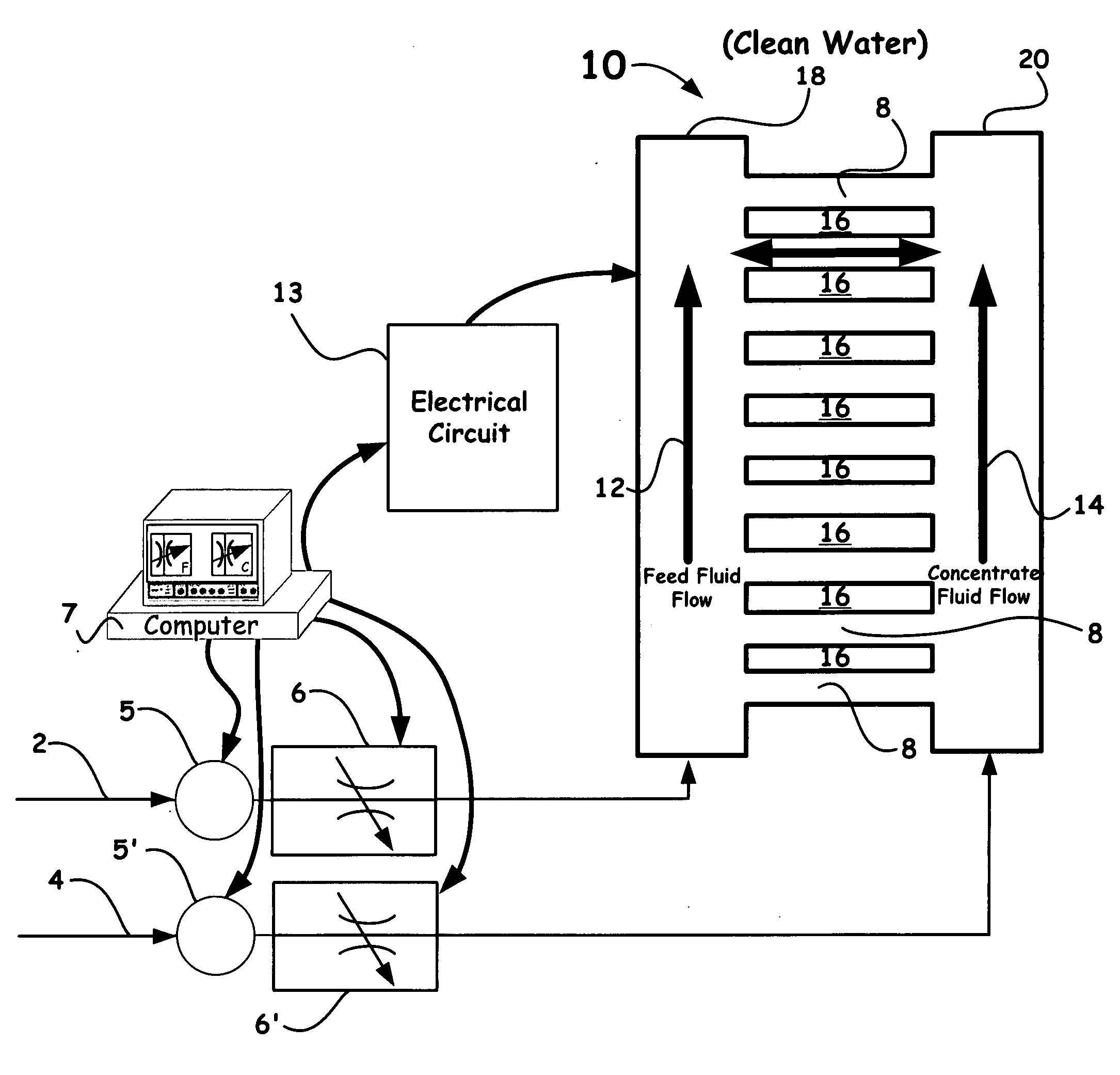
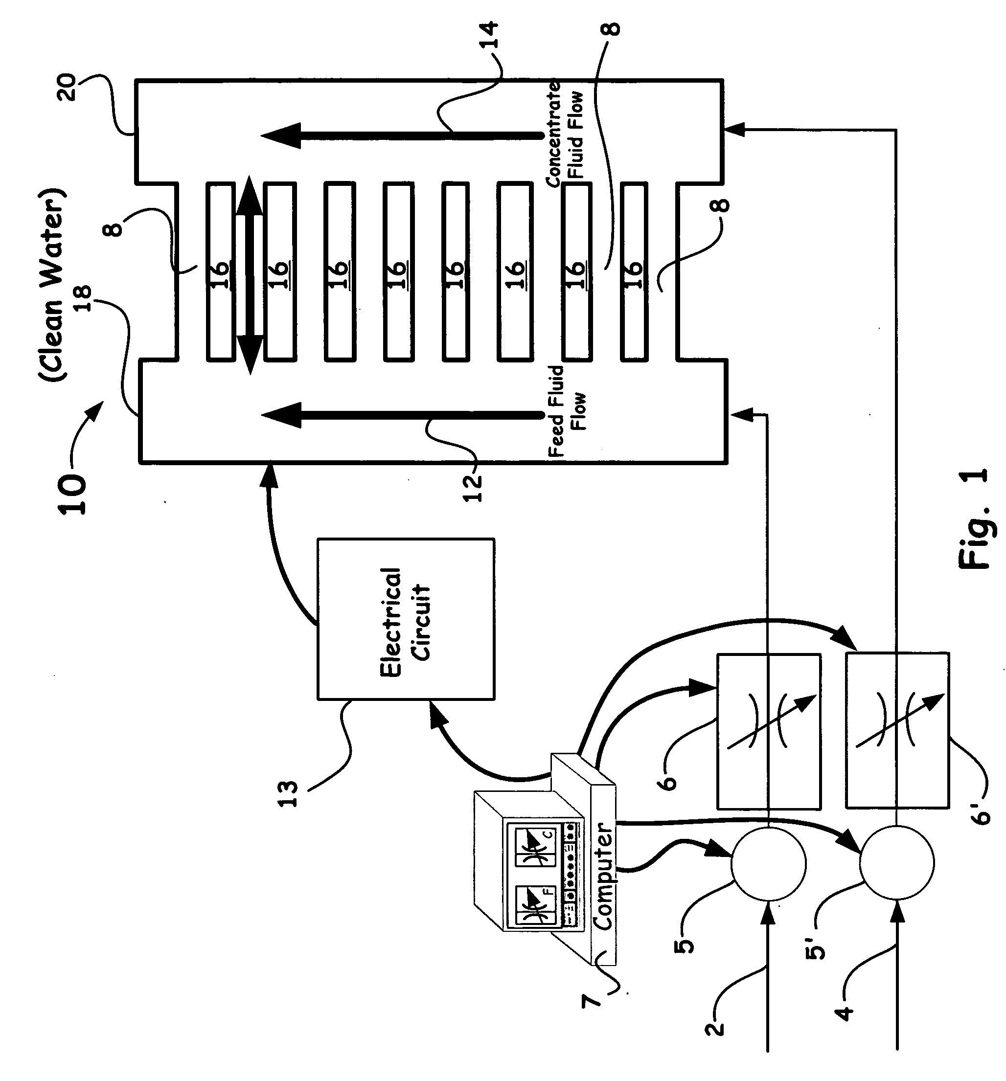
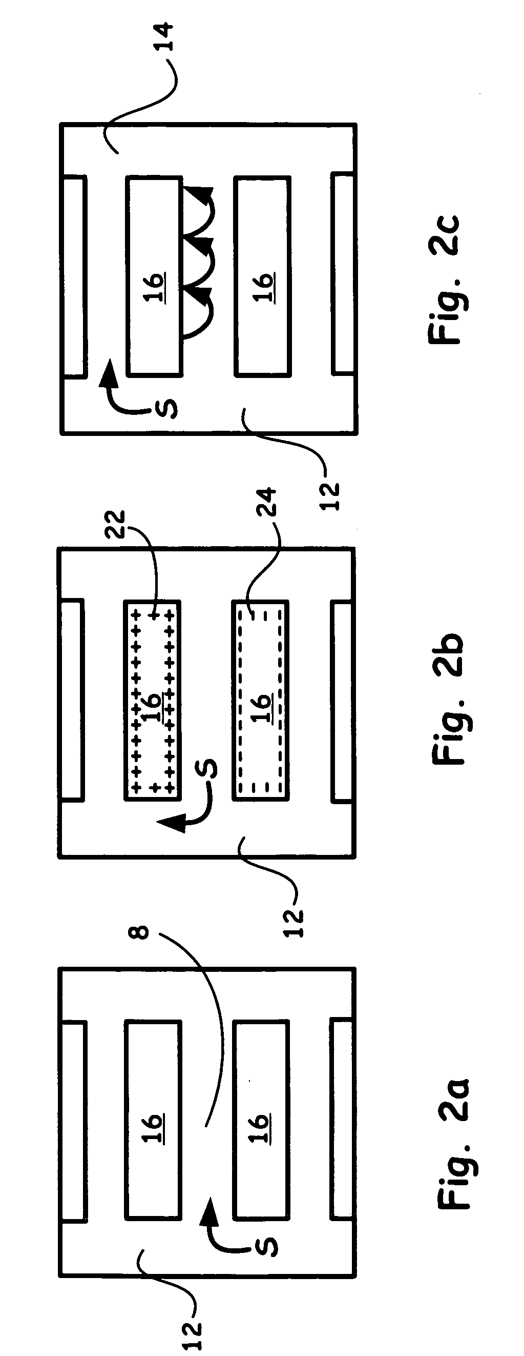
[0023] Referring now to the drawings, specific embodiments of the invention are shown. The detailed description of the specific embodiments, together with the general description of the invention, serves to explain the principles of the invention.

[0024] Unless otherwise indicated, all numbers expressing quantities of ingredients, constituents, reaction conditions and so forth used in the specification and claims are to be understood as being modified in all instances by the term “about”. Accordingly, unless indicated to the contrary, the numerical parameters set forth in the specification and attached claims are approximations that may vary depending upon the desired properties sought to be obtained by the subject matter presented herein. At the very least, and not as an attempt to limit the application of the doctrine of equivalents to the scope of the claims, each numerical parameter should at least be construed in light of the number of reported significant digits and by applyin...


PUM

PropertyMeasurementUnit
Lengthaaaaaaaaaa
Lengthaaaaaaaaaa
Lengthaaaaaaaaaa

Abstract

The present invention provides a new method and apparatus/system for purifying ionic solutions, such as, for example, desalinating water, using engineered charged surfaces to sorb ions from such solutions. Surface charge is applied externally, and is synchronized with oscillatory fluid movements between substantially parallel charged plates. Ions are held in place during fluid movement in one direction (because they are held in the electrical double layer), and released for transport during fluid movement in the opposite direction by removing the applied electric field. In this way the ions, such as salt, are “ratcheted” across the charged surface from the feed side to the concentrate side. The process itself is very simple and involves only pumps, charged surfaces, and manifolds for fluid collection.

Description

RELATED APPLICATION [0001] This application claims the benefits of U.S. Provisional Application No. 60 / 761,484, filed Jan. 23, 2006, and entitled, “DESALINATION USING ELECTROSTATIC ION PUMPING,” which is incorporated herein by reference in its entirety.[0002] The United States Government has rights in this invention pursuant to Contract No. W-7405-ENG-48 between the United States Department of Energy and the University of California for the operation of Lawrence Livermore National Laboratory.BACKGROUND OF THE INVENTION [0003] 1. Field of the Invention [0004] The present invention relates to a separation method and apparatus / system for removing ions, contaminants and impurities from fluids such as water and other aqueous process streams, and more particularly, the present invention relates to a separation method and apparatus / system for desalinating water that uses engineered charged surfaces to sorb ions from salt solutions. [0005] 2. Description of Related Art [0006] Conventionally...

Claims


Application Information

Patent Timeline
IPC IPC(8): B01D61/42
CPCB01D61/422B01D61/44B01D2311/2603B01D2313/48C02F1/4604C02F2201/46175C02F2001/46152C02F2103/08C02F2201/4611C02F2201/46125C02F2201/46145C02F1/4691Y02A20/124Y02A20/131
Inventor BOURCIER, WILLIAM L.AINES, ROGER D.HASLAM, JEFFERY J.SCHALDACH, CHARLENE M.O'BRIEN, KEVIN C.CUSSLER, EDWARD
Owner RGT UNIV OF MINNESOTA
Why Eureka
Try Eureka