Injector for injecting fuel into combustion chambers of internal combustion engines, in particular a piezoelectric-actuator-controlled common rail injector

a common rail and injector technology, applied in the direction of fuel injectors, machines/engines, mechanical equipment, etc., can solve the problems of requiring comparatively large engineering effort and expense at the sealing face of injectors

Inactive Publication Date: 2007-07-26
ROBERT BOSCH GMBH
View PDF4 Cites 12 Cited by
  • Summary
  • Abstract
  • Description
  • Claims
  • Application Information

AI Technical Summary

Benefits of technology

[0005] According to the invention, this object is attained, in an injector of the generic type defined at the outset, by the definitive characteristics of claim 1.
[0006] Advantageous refinements of the fundamental concept of the invention can be learned from claims 2-10.
[0007] By means of the invention, an integration of the valve plate into the retaining body that receives the booster piston is accomplished. This advantageously means that one complete sealing level is dispensed with. The entire system is simplified substantially as a result, and more-economical production of the injector is made possible.

Problems solved by technology

In general, such injectors require comparatively major engineering effort and expense at the sealing faces, especially in the high-pressure region.

Method used


Image

  • Injector for injecting fuel into combustion chambers of internal combustion engines, in particular a piezoelectric-actuator-controlled common rail injector
  • Injector for injecting fuel into combustion chambers of internal combustion engines, in particular a piezoelectric-actuator-controlled common rail injector

Examples


Embodiment Construction

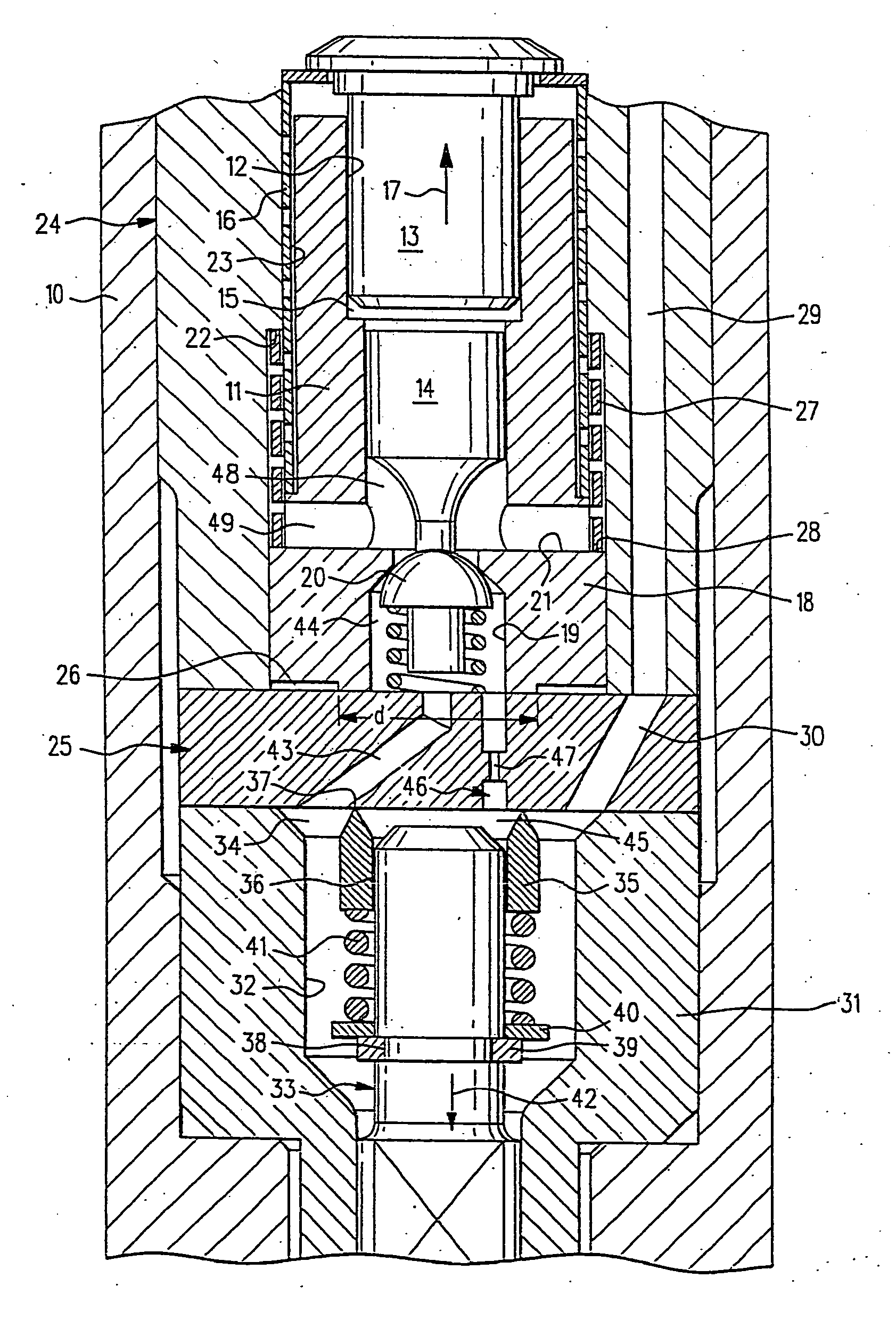
[0009] Reference numeral 10 indicates an injector body of a CR injector—intended in particular for use in diesel engines. A sleevelike booster housing 11 with an offset central axial bore 12 is located in the injector body 10, and a piezoelectric actuator 13 and a booster piston 14 are received axially displaceably in this housing. Between the piezoelectric actuator 13 and the booster piston 14 a booster chamber 15 is embodied. The piezoelectric actuator 13 (which is connected to an electrical power supply in the usual manner which is therefore not shown) is prestressed in the direction of an arrow 17, or in other words counter to the direction of action of the piezoelectric actuator 13, by a prestressing spring 16 that surrounds the booster housing 11 and is embodied as a tube spring.

[0010] A valve plate identified overall by reference numeral 18 is embodied in the axial extension of the booster housing 11, and in an offset axial bore 19 it receives a control valve 20.

[0011] A su...


PUM


Abstract

A common rail injector for an internal combustion engines has control means including a piezoelectric actuator deposed in an injector body and via at least one booster piston actuates a control valve received in a valve plate. Also provided are a nozzle body having a nozzle outlet on its free end toward the combustion chamber; a nozzle needle located axially movably and actuatably in a longitudinal recess of the nozzle body; a throttle disk, closing off the rear end (remote from the nozzle outlet) of the longitudinal recess and located between the nozzle body and the control valve, which throttle disk forms an opening stop for the nozzle needle and cooperates with the rear end face of the nozzle needle and thus limits the opening stroke of the nozzle needle; and a control chamber between the rear nozzle needle end face and the throttle disk, which chamber is in hydraulic communication with a pressure connection serving to deliver fuel. A substantial special feature is that a cylindrical retaining body is disposed in the injector body and receives the booster piston or pistons and the valve plate that contains the control valve.

Description

PRIOR ART [0001] The invention relates to an injector as generically defined by the preamble to claim 1. [0002] A CR injector of this type is known from German Patent Disclosure DE 199 36 668 A1. A similar injector is also shown by DE 102 41 462 A1. A CR injector in which the booster piston is actuated by a piezoelectric actuator is known from German Patent DE 195 19 191 C2. [0003] In general, such injectors require comparatively major engineering effort and expense at the sealing faces, especially in the high-pressure region. [0004] The object of the invention is to reduce this effort and expense at the sealing faces. ADVANTAGES OF THE INVENTION [0005] According to the invention, this object is attained, in an injector of the generic type defined at the outset, by the definitive characteristics of claim 1. [0006] Advantageous refinements of the fundamental concept of the invention can be learned from claims 2-10. [0007] By means of the invention, an integration of the valve plate i...

Claims


Application Information

Patent Timeline
Patent Type & Authority Applications(United States)
IPC IPC(8): B05B1/08F02M63/00F02M47/02F02M59/46
CPCF02M47/027F02M63/0026F02M2547/001F02M2200/703F02M63/0045F02M59/46F02M63/00F02M47/02
Inventor BOECKING, FRIEDRICH
Owner ROBERT BOSCH GMBH
Why Eureka
Try Eureka