Pneumatic pinch valve

a pneumatic pinch valve and valve body technology, applied in the direction of diaphragm valves, valve details, valve arrangements, etc., can solve the problems of difficult prevention, difficult to control the flow passage, and the fluid cannot be leaking, so as to achieve maximum durability, not easily deteriorated during long-time operation, and simple construction of pneumatic pinch valves

Active Publication Date: 2007-07-26
SHENZHEN MINDRAY BIO MEDICAL ELECTRONICS CO LTD
View PDF10 Cites 26 Cited by
  • Summary
  • Abstract
  • Description
  • Claims
  • Application Information

AI Technical Summary

Benefits of technology

[0005]The object of the present invention is to provide a pneumatic pinch valve which has a simple construction and is capable of preventing the earlier fatigue or breakage of the fluid tubes during the long-time operation.
[0013]In comparison with the prior art, the pneumatic pinch valve of the present invention has the following advantages:
[0014]1) Since the pneumatic pinch valve is communicated with the air source via the air inlet port and controls the interception and release of fluid in the tube in a pneumatic manner, the construction of the pneumatic pinch valve is simple. Moreover, since the pressure of the air source can be adjusted, i.e. adjusting the pinching force applied to the fluid tube, the fluid tube is not easily deteriorated during long-time operation.
[0015]2) Since the adjusting gasket with different thickness can be used to adjust the distance between the pressing piece and the lever, the fluid tube may operate all the way under the optimal pressurized amount, which not only prevents the fluid in the fluid tube from leaking under the maximum pressure, but also makes the fluid tube have maximum durability.

Problems solved by technology

In the current Hematology Analyzer, the control of flow passage is relatively complex due to a number of tubes, large flow of fluid and high requirement for clearness.
In addition, since the fluid in the flow passage has strong corrosiveness, leakage of the fluid is not permitted.
Due to the construction of the solenoid valve, it is hard to prevent the residual contamination resulted from the dead region inside the solenoid valve which can not be cleaned during cleaning the solenoid valve.
Moreover, the pressure loss is relatively large when the fluid flows through the solenoid valve.
Therefore, such a solenoid valve is only adapted to such a case that the clearness is not required, corrosiveness of fluid is not strong and the fluid flow is not large.
However, the above control has the following defects: heavy defect will be presented in the case of long-time interception and short-time release.
If the normal-opening type of solenoid pinch valve is used, the solenoid pinch valve will operate with electricity for long time during the interception of the fluid, so that the amount of the generated heat is large and the durability of the solenoid pinch valve will be affected.
If a normal-closing type of solenoid pinch valve is used, there is no problem during operation of the solenoid pinch valve, but when the solenoid pinch valve is not in the operating state, the fluid tube is always in the pinched state, which might result in fatigue break of the fluid tube and the adhesion of the inner wall thereof the fluid tube and.
For assuring enough pinching force, the solenoid pinch valve is relatively bulky; however, since the heat productivity of bulky solenoid pinch valve is relatively high, the heat dissipation should be considered in the case that the valve operates for a long time and in the case that multiple solenoid pinch valves operate at the same time.
In addition, the optimal pressed state can not be set according to different materials and different wall thicknesses of the fluid tubes.
Noise is large during operation of the solenoid pinch valve and the manufacturing cost of the solenoid pinch valve is high.

Method used


Image

  • Pneumatic pinch valve
  • Pneumatic pinch valve
  • Pneumatic pinch valve

Examples


first embodiment

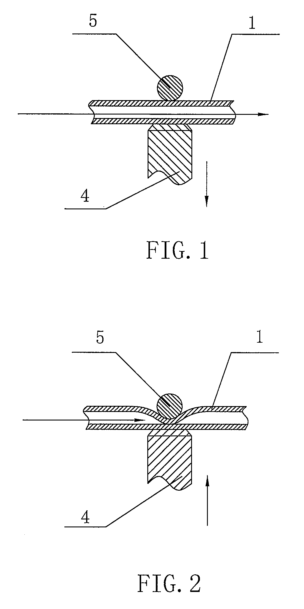
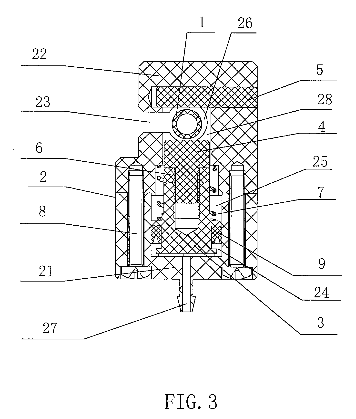
[0021]Hereinafter, the present invention will be described with reference to FIGS. 3-5. The pneumatic pinch valve of the present invention uses a single acting cylinder as a power mechanism. In an operating state (i.e. an intercepting state) of the pneumatic pinch valve, an external pressure is applied to a fluid tube 1 so as to pinch an inner wall of the fluid tube 1 in a contacting-closed state, and thus the fluid in the fluid tube 1 is intercepted. The fluid tube 1 is made of a relatively soft and resilient material, so that the inner wall of the fluid tube 1 may be deformed into a fatten shape in a contacting-closed state and then the fluid tube 1 is closed when a preset external pressure is applied to the fluid tube 1, and the inner wall of the fluid tube 1 may be recovered to its initial shape when the preset external pressure is withdrawn.

[0022]The pneumatic pinch valve of the present invention includes a main body 2, a piston 3, a pressing piece 4 and a lever 5. An opening 2...

second embodiment

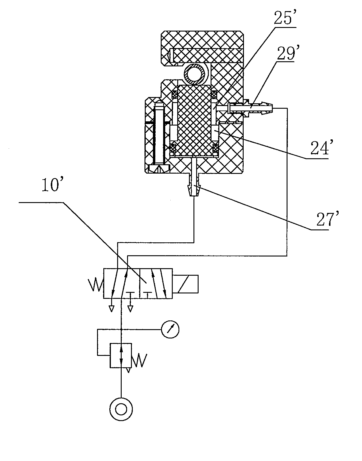
[0031]It should be noted that the present invention may be implemented without limitation of the above embodiments. On a basis of the construction of the second embodiment, a resilient element 7 may be further provided around the piston, and thus the piston may be urged by this resilient element 7, the second cavity 25′ and the air inlet port 29′ of the second cavity 25′ together.

[0032]In the present invention, the power may be provided to pinch the fluid tube in a pneumatic-driving mode with simple construction, and different magnitude of pinching forces may be obtained by selecting different pressure of the air source or adjusting pressure regulating valve. For different fluid tubes, the optimal or adjustable pressing amount can be set. Each fluid tube may have desired durability for the case that the fluid tube is pinched with constant pressurized amount, variation of the pinching force resulted from the fluctuation of air pressure is prevented, and unreliability of the pinching ...


PUM


Abstract

The present invention provides a pneumatic pinch valve, comprising: a lever and a pressing piece, a fluid tube receiving space being formed between the lever and the pressing piece, wherein the pneumatic pinch valve further comprises a main body providing a cavity therein, the lever being installed on the main body; a piston provided in the cavity of the main body, the piston engaging with an inner wall of the cavity of the main body so as to divide the cavity into a first cavity and a second cavity, the pressing piece being positioned in the second cavity and supported on the piston; an air inlet port provided at the first cavity, wherein air introduced into the first cavity via the air inlet port moves the piston toward the fluid tube receiving space so as to press the fluid tube through an engagement of the pressing piece on the piston with the lever, and thus intercept the fluid in the fluid tube; and an air discharge mechanism provided at the piston, by which the piston pushes the air introduced into the first cavity, and then discharges the air into outside, so that the pressing piece releases the fluid tube to allow the intercepted fluid to flow through the fluid tube. Since the pneumatic pinch valve is communicated with the air source via the air inlet port and controls the interception and release of fluid in the flow passage in a pneumatic manner, the construction of the pneumatic pinch valve is simple. Moreover, since the pressurized amount of the fluid tube or the pressure of the air source can be adjusted, i.e. adjusting the pinching force applied to the fluid tube, the fluid tube is not easily deteriorated during long-time operation.

Description

FIELD OF THE INVENTION[0001]The present invention relates to a technical field of analysis on blood cells, and more particularly, relates to a valve for controlling the flow of fluid in a fluid tube so that the fluid flow is prevented (referred as “interception” hereinafter)or the fluid can flow through the tube (referred as “release” hereinafter).BACKGROUND OF THE INVENTION[0002]In the current Hematology Analyzer, the control of flow passage is relatively complex due to a number of tubes, large flow of fluid and high requirement for clearness. In addition, since the fluid in the flow passage has strong corrosiveness, leakage of the fluid is not permitted. In order to meet these requirements, a solenoid valve and a solenoid pinch valve are generally used to intercept and release the fluid in the flow passage.[0003]For the solenoid valve, the fluid directly contacts with a valve cavity and a valve port of the solenoid valve during passing though the solenoid valve. Due to the constru...

Claims


Application Information

Patent Timeline
Patent Type & Authority Applications(United States)
IPC IPC(8): F16K7/04
CPCF16K31/122F16K7/06
Inventor LI, LECHANGYAN, YAN
Owner SHENZHEN MINDRAY BIO MEDICAL ELECTRONICS CO LTD
Why Eureka
Try Eureka