Light emitting module and process thereof

a technology of light emitting diodes and light-emitting modules, which is applied in the direction of light-emitting devices, transportation and packaging, light-emitting devices, etc., can solve the problems of reducing efficiency, reducing the efficiency of light-emitting diodes, so as to reduce the temperature and reduce the effect of conducting heat energy

Inactive Publication Date: 2007-07-26
CHEN CHIEN CHUNG
View PDF7 Cites 19 Cited by
  • Summary
  • Abstract
  • Description
  • Claims
  • Application Information

AI Technical Summary

Benefits of technology

[0009]In view of this, one object of the present invention provides a light emitting module and process thereof to conduct heat energy more effectively and quickly and further reduces the temperature of an LED according to a medium and process thereof that is able to conduct both electricity and heat.

Problems solved by technology

However, a big problem is how to overcome the usage life being shortened and efficiency reduced due to excessive temperatures.
However, for conducting heat for a high power light emitting diode 2, the silver epoxy 20 is still deficient, and that makes the light emitting diode 2 heat dissipation comparatively slow.
Even after installing additional heat dissipation mediums (such as a Heat Sink) under the metal substrate 1 or the bearing base 5, it is still unable to dissipate more heat because the actual heat energy is unable to be conducted to the heat dissipation medium effectively.
However, in reality, the light emitting diode 2 itself is in danger of being damaged, because the heat energy is unable to be conducted.
In order to improve the heat dissipation performance, silver epoxy 20 with high thermal conductivity can be used, however it will be too expensive to build a reasonably low cost commercial product.
Moreover, if it is used on a higher power LED module, it is still not good enough to conduct heat energy effectively and quickly.

Method used


Image

  • Light emitting module and process thereof
  • Light emitting module and process thereof
  • Light emitting module and process thereof

Examples


Embodiment Construction

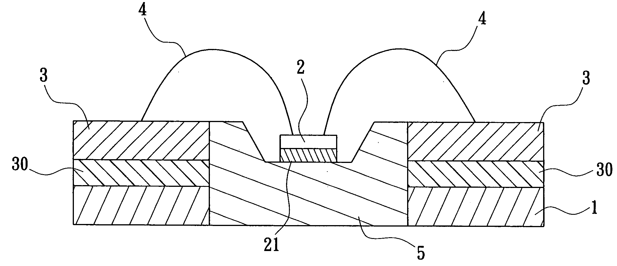
[0023]FIG. 3 is a structural cross-sectional view which illustrates a light emitting module according to an embodiment of the present invention. As shown by FIG. 3, the present invention provides a light emitting module comprising a metal substrate 1, at least one LED 2, a printed circuit board 3, at least one conductive wire 4 and a bearing base 5. The bearing base 5 is disposed on the metal substrate 1, and the printed circuit board 3 is stuck on the metal substrate 1 through an insulation colloid 30. The LED 2 is adhered on the bearing base 5 through a compound metal via the method of eutectic soldering. The LED 2 is electrically connected to the printed circuit board 3 though the conductive wires 4 separately. Wherein, the compound metal 21 may consist of gold and tin (or silver and tin) which is a medium with high thermal conductive coefficient. Because of the characteristic of the compound metal 21, it is able to conduct more effectively the heat energy which is produced by th...


PUM


Abstract

A light emitting module includes a metal substrate, a bearing base, at least one LED, a printed circuit board, and at least one conductive wire. A first perforation is formed on the metal substrate and the bearing base is embedded into the first perforation of the metal substrate. According to an eutectic soldering method, the LED(s) is / are adhered on the bearing base by a compound metal. A second perforation is formed on the printed circuit board to expose the LED(s) which is / are adhered on the bearing base and further allows the printed circuit board to stick on the metal substrate. The conductive wires are used to connect electrically the LED(s) with the printed circuit board.

Description

BACKGROUND OF THE INVENTION[0001]1. Field of the Invention[0002]The present invention is generally related to a light emitting module and process thereof, and more particularly, a light emitting diode used as a lighting source for the light emitting module and process thereof.[0003]2. Description of Related Art[0004]Over recent years the technology behind light emitting diodes has developed rapidly, especially compared to that of traditional Incandescent Lamps. HP LEDs (High-power light emitting diodes) are seen as better illumination devices because the over greater power saving, a longer usage life, high durability and faster responding speeds. Because of these advantages, light emitting diodes have become more common in different fields, such as the general lighting market, public works and for automobiles. Further facilitating these are other markets that require this kind of light emitting diodes which are continuing to grow.[0005]However, a big problem is how to overcome the u...

Claims


Application Information

Patent Timeline
Patent Type & Authority Applications(United States)
IPC IPC(8): H01L23/02
CPCF21K9/00H01L33/641H01L33/642H01L2224/48091H01L2224/48247Y10S362/80H01L2224/73265H01L2924/00014
Inventor CHEN, CHIEN CHUNG
Owner CHEN CHIEN CHUNG
Why Eureka
Try Eureka