Centrifugal motor-compressor unit

a compressor unit and centrifugal technology, applied in the direction of bearings, shafts, liquid fuel engines, etc., can solve the problems of reducing generating greater losses than the motor. , to achieve the effect of improving the cooling efficiency of the compressor unit, reducing the size of the air gap, and increasing the flow ra

Active Publication Date: 2007-07-26
THERMODYN
View PDF6 Cites 52 Cited by
  • Summary
  • Abstract
  • Description
  • Claims
  • Application Information

AI Technical Summary

Benefits of technology

[0014] It has been found that such an arrangement improves considerably the cooling within the compressor unit. Specifically, it has been found that the size of the air gap of the magnetic bearings compared with the size of the air gap of the motor detracts from cooling when the same flow is used to cool the bearings and the motor, by preventi

Problems solved by technology

Specifically, it has been found that the size of the air gap of the magnetic bearings compared with the size of the air gap of the motor detracts from cooling when the same flow is used to cool the

Method used


Image

  • Centrifugal motor-compressor unit
  • Centrifugal motor-compressor unit
  • Centrifugal motor-compressor unit

Examples


Embodiment Construction

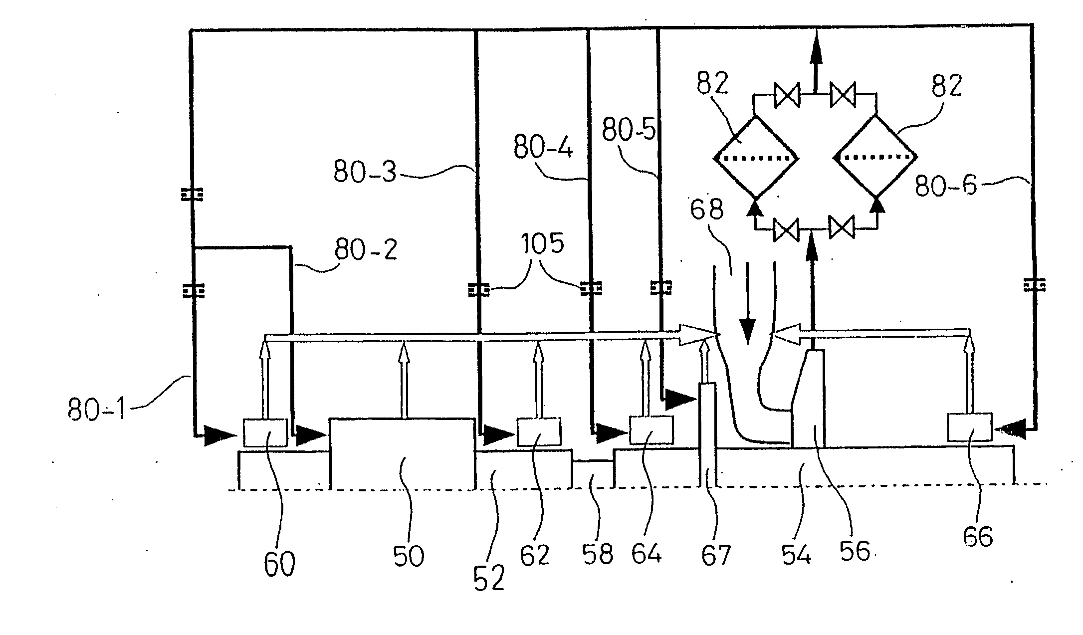
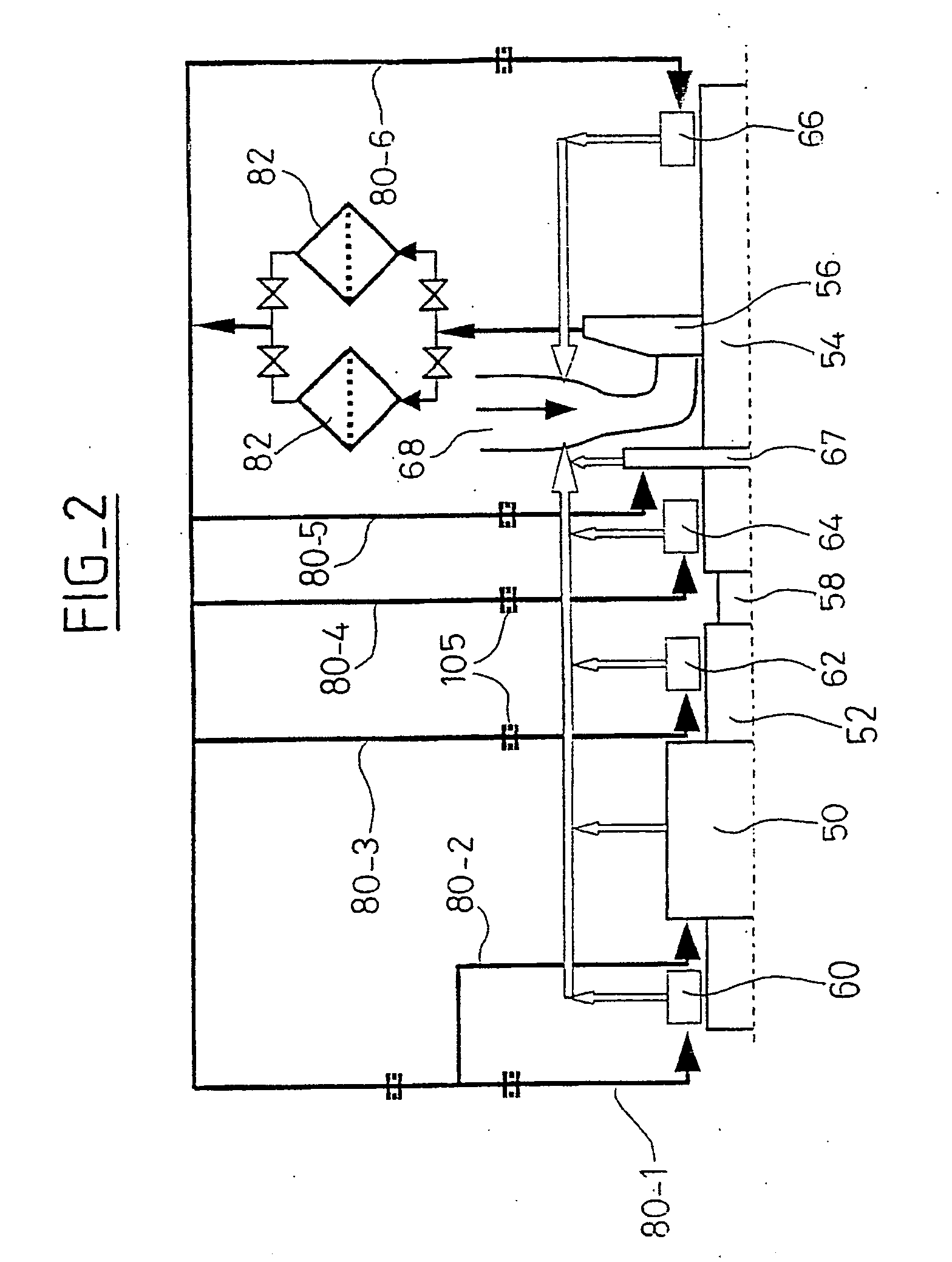
[0028]FIG. 2 depicts just one compression stage for reasons of clarity, the other compression stages not having been depicted. It will, however, be appreciated that it may be provided with any number of compression stages, as will be discussed later with reference to FIGS. 3 to 6.

[0029] The compressor unit illustrated in this FIG. 2 includes a motor means 50, consisting for example of a variable high-speed electric motor rotationally driving a rotor 52, itself driving, at the same speed, a driven shaft 54 on which an impeller wheel 56 is mounted. The rotor 52 and the driven shaft 56 are connected via a flexible coupling 58. As a result, the rotor 52 and the driven shaft 54 are each supported by two end radial bearings 60, 62 and 64, 66, respectively. A thrust bearing 67 limits the axial displacement of the rotor 54 when the compressor is in operation, this displacement being caused by the appearance of axial forces that are due to the appearance of a differential pressure across th...


PUM


Abstract

A centrifugal compressor unit includes a driving means for rotatably driving a rotor, and at least one compressor including a statoric body and an arrangement of blade wheels mounted on a shaft which is rotatably driven by the rotor in the statoric body. The group formed by the motor and/or each compressor being mounted in a common housing is sealed from the gas used by the compressor. The compressor unit also includes an arrangement of active bearings for axially and radially guiding the rotor and the driven shaft, and a means for cooling the driving means and the guiding bearings by withdrawing the gas used by the compressor at the outlet of a first compression stage. The cooling means includes a set of internal conduits for supplying the driving means and the bearings with cooling gas. The cooling gas flow in the motor and the cooling gas flow in the bearing is separated and then converge upstream of the first compression stage.

Description

BACKGROUND OF THE INVENTION [0001] 1. Field of the Invention [0002] The invention relates to a centrifugal compressor unit. More specifically, the invention relates to a centrifugal compressor unit of the integrated type, that is to say of the type in which the compressor and a motor means for driving the compressor are mounted in a common housing sealed against the gas handled by the compressor. [0003] 2. Brief Description of the Related Art [0004] With reference to FIG. 1, a conventional integrated compressor unit includes a motor means, generally including an electric drive motor 10 and a centrifugal compressor 12 including, for example, several compression stages, the entity being mounted in a common housing sealed against the gas handled by the compressor. [0005] As can be seen in FIG. 1, the motor 10 rotationally drives a rotor 16 itself rotationally driving a driven shaft 18 supporting a set of compression impeller wheels 20, 22, 24 and 26. [0006] In the example of a compress...

Claims


Application Information

Patent Timeline
IPC IPC(8): F04B17/00F04D25/06F04D29/58
CPCF04D25/0606F04D29/584F16C32/0489F16C37/005F16C32/0461F04D17/122F04D29/058F04D29/5806F16C2360/44
Inventor LABOUBE, PIERREFRIEZ, PATRICKPUGNET, JEAN-MARCBONNEFOI, PATRICE
Owner THERMODYN
Why Eureka
Try Eureka