Flow restricting devices in pumps

a technology of flow restricting device and pump, which is applied in the direction of piston pump, positive displacement liquid engine, liquid fuel engine, etc., can solve problems such as sub-core damag

Inactive Publication Date: 2007-07-26
CURTISS WRIGHT ELECTRO MECHANICAL
View PDF29 Cites 37 Cited by
  • Summary
  • Abstract
  • Description
  • Claims
  • Application Information

AI Technical Summary

Benefits of technology

[0011] Further, there is broadly contemplated herein, in accordance with at least one presently preferred embodiment of the present invention, a rotary pump comprising: a motor; a shaft member extending from the motor; an impeller attached to a free end of the shaft member; a housing which encloses a major portion of the shaft member; the housing comprising a seal housing which circumscribes at least a portion of the shaft member, the seal housing including at least one sealing element for restricting fluid flow along the shaft member; the motor being configured for rotating the shaft in a manner to drive the impeller; and an arrangement for restricting fluid flow along the shaft relative to the seal housing in at least one annular space defined between the shaft member and the seal housing; the fluid flow restricting arrangement comprising a discontinuous ring member disposed about the shaft member; the discontinuous ring member having two ends; the discontinuous ring member being actuable between: a first condition, wherein the ends are spaced apart over a first distance; and a second condition, wherein the ends are spaced apart over a second distance, the second distance being less than the first distance; wherein, in the first condition, a greater flow path for fluid is afforded, in the at least one annular space defined between the shaft member and the seal housing, than in the second condition.

Problems solved by technology

In the case of nuclear reactor coolant pumps, since pump sealing assemblies can be prone to failure, e.g. in response to unmitigated high temperatures of reactor coolant, any resultant excessive leakage rates could lead to reactor coolant uncovering of a reactor core, and subsequent core damage.

Method used


Image

  • Flow restricting devices in pumps
  • Flow restricting devices in pumps
  • Flow restricting devices in pumps

Examples


Embodiment Construction

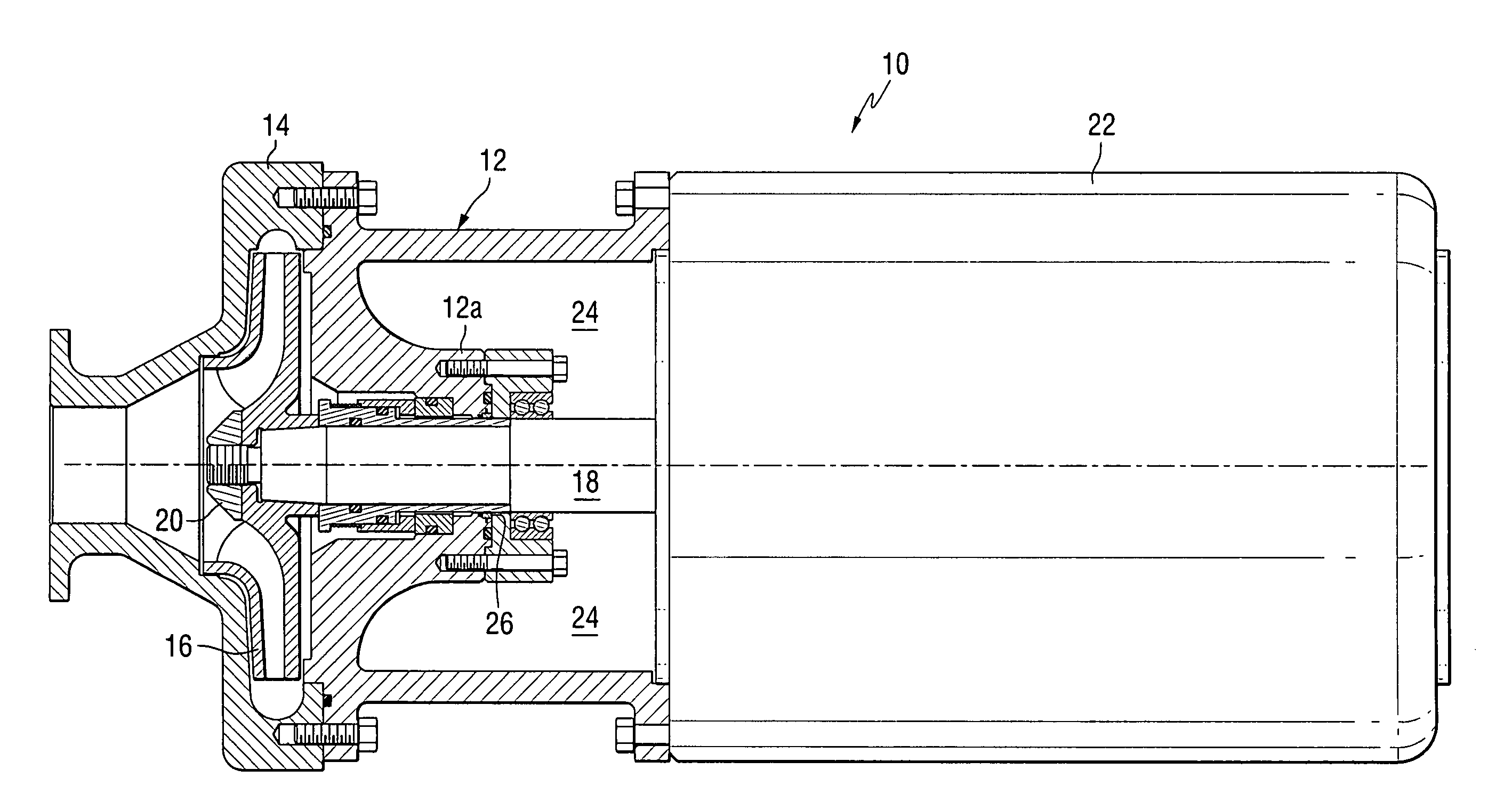
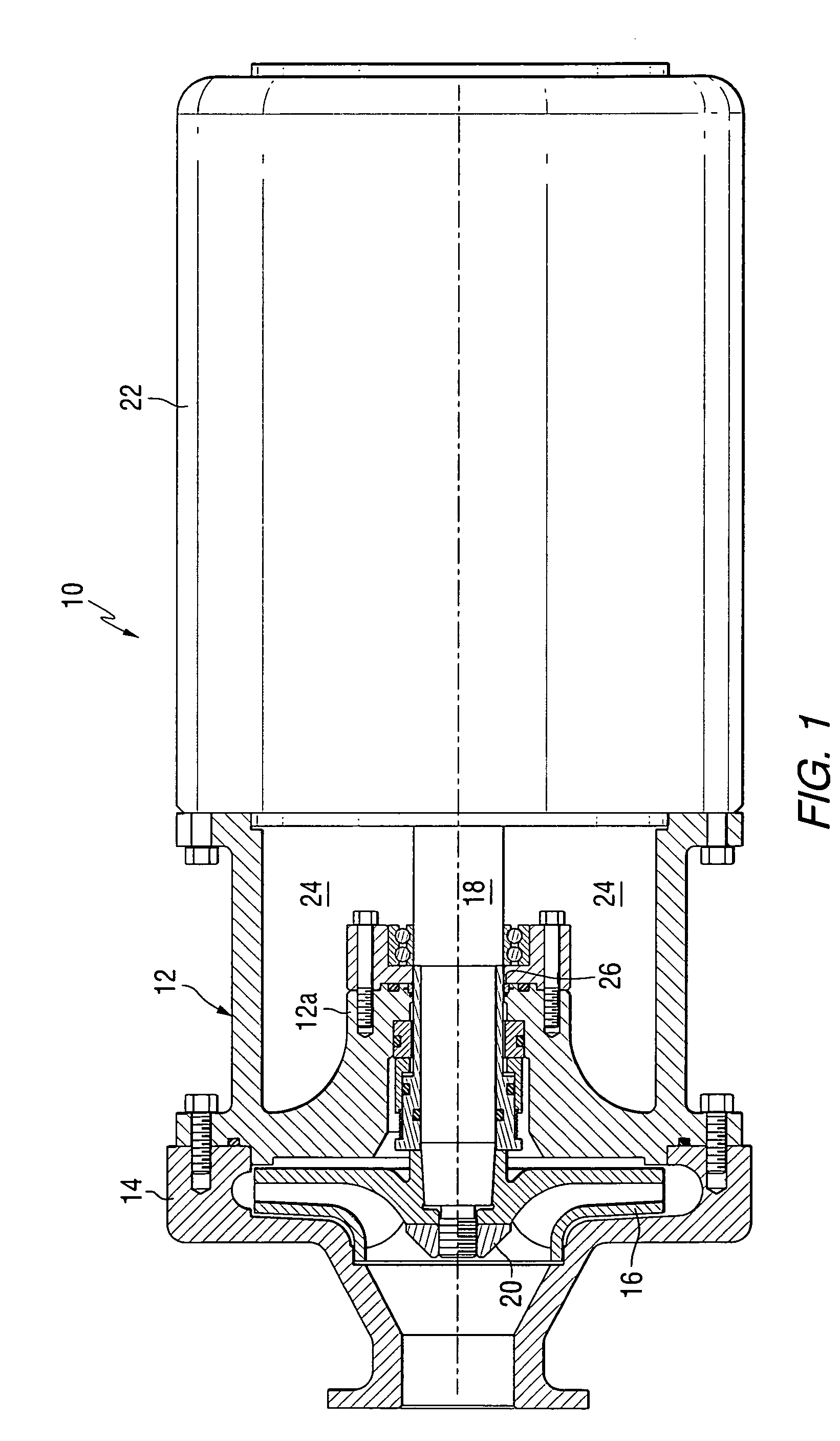
[0031] Referring to FIG. 1, a pump 10 generally includes a main pump housing 12. While, in the embodiment shown, housing 12 forms a large portion of an external housing for pump 10, it retracts inwardly to further form an internal seal housing 12a. An impeller housing 14 is also bolted to the main pump housing 12 and houses an impeller 16. Pump 10 can be representative of a wide variety of rotary pumps, including general centrifugal pumps, nuclear reactor coolant pumps and chemical processing pumps (e.g., as commonly used in the chemical processing industry). Pump 10 may be oriented in any direction appropriate for the application at hand, e.g., a generally horizontal direction or (in the case of a reactor coolant pump) in a generally vertical direction.

[0032] The pump 10 includes a pump shaft 18 extending centrally with respect to the pump housing 12 and being sealingly and rotatably mounted within the seal housing 12a. Pump shaft 18, at one end thereof, is connected to impeller 1...


PUM


Abstract

Restriction of flow along a shaft by interposing a split ring in the annulus between the shaft and housing. When the ends of the split ring are separated, the effective diameter of the ring is increased and a clearance between the ID of the split ring and the shaft is maintained permitting flow. When the ends are released and allowed to come together the split ring closes the annular gap and restricts the flow. Also contemplated is the restriction of flow along a shaft by interposing an axially movable sleeve in the annulus between the shaft and housing. Flow through the annulus between the movable sleeve and the shaft is resisted by the clearance or features such as labyrinths, to thereby create a differential pressure from one end of the sleeve to the other.

Description

FIELD OF THE INVENTION [0001] The present invention generally relates to rotary pumps, such as chemical processing pumps or nuclear reactor coolant pumps, and constituent components therefor, such as flow restricting devices. BACKGROUND OF THE INVENTION [0002] In pressurized water nuclear power plants, a reactor coolant system is used to transport heat from the reactor core to steam generators for the production of steam. The steam is then used to drive a turbine generator. The reactor coolant system includes a plurality of separate cooling loops, each connected to the reactor core and containing a steam generator and a rotary coolant pump. Other venues also present situations where containment of a process fluid is critical, such as in the case of rotary chemical processing pumps. [0003] A rotary pump such as a reactor coolant pump or chemical processing pump typically is a centrifugal pump designed to move large volumes of process fluid (e.g., reactor coolant) at high temperatures...

Claims


Application Information

Patent Timeline
Patent Type & Authority Applications(United States)
IPC IPC(8): F04B17/00
CPCF04D15/00F04D29/126F04D29/106F16J15/164
Inventor JANOCKO, DAVID JEFFREY
Owner CURTISS WRIGHT ELECTRO MECHANICAL
Why Eureka
Try Eureka