Digital Filter Design System And Method

a filter design and digital filter technology, applied in the field of digital signal processing, can solve the problems of additional group delay, general cost of implementation, and the technique described does not include the use and the modification of an allpass filter to correct a limited amount of phase with a controllable amount of overall group delay

Inactive Publication Date: 2007-07-26
CLARITY EQ
View PDF8 Cites 7 Cited by
  • Summary
  • Abstract
  • Description
  • Claims
  • Application Information

AI Technical Summary

Benefits of technology

[0008] It is an object of the present invention to provide an improved filter design.
[0010] The predetermined phase properties can include minimizing the group delay of the allpass filter. The allpass filter can be a Finite Impulse Response filter created from a windowed response of an Infinite Impulse Response filter. In some embodiments, the window of the windowed response can comprise either a rectangular window or a Hanning window. Preferably, the Finite Impulse Response filter has a phase response approximating the Infinite Impulse Response to a predetermined error measure. The shape or size of the window can be adjusted to meet the predetermined error measure. Also, the delay of the Finite Impulse Response filter can be adjusted to meet the predetermined error measure.
[0011] In accordance with a further aspect of the present invention, there is provided a method of designing a finite impulse response filter approximating an infinite impulse response allpass filter, the finite impulse response filter maximizing the group delay correction whilst simultaneously reducing the overall group delay and keeping the overall filter error within a predetermined tolerance, the method comprising the steps of: (a) from an initial maximum group delay correction value, determining a corresponding first allpass filter which minimizes its overall group delay; (b) if the resultant first allpass filter has a maximum group delay correction and the resultant finite impulse response filter is within the predetermined error tolerance, decreasing the amount of group delay; (c) otherwise, increasing the amount of group delay correction; (d) iterating through steps (a) to (c) until the method converges.
[0014] In accordance with a further aspect of the present invention, there is provided a method of linearising the phase of a linear time-invariant filter with arbitrary magnitude and phase response whilst controlling the amount of overall delay introduced by the resulting linearisation.

Problems solved by technology

FIR filters, on the other hand, can be designed to have linear-phase response and hence no temporal distortion, but are generally more costly to implement due to the large number of arithmetic operations performed per sample of input.
However, the techniques described do not include using an allpass filter, or a modified allpass filter correcting a limited amount of phase with a controllable amount of overall group-delay.
In fact, their techniques introduce additional group-delay and have no discussion of minimising the group delay.

Method used


Image

  • Digital Filter Design System And Method
  • Digital Filter Design System And Method
  • Digital Filter Design System And Method

Examples


Embodiment Construction

Description of the Preferred and Other Embodiments

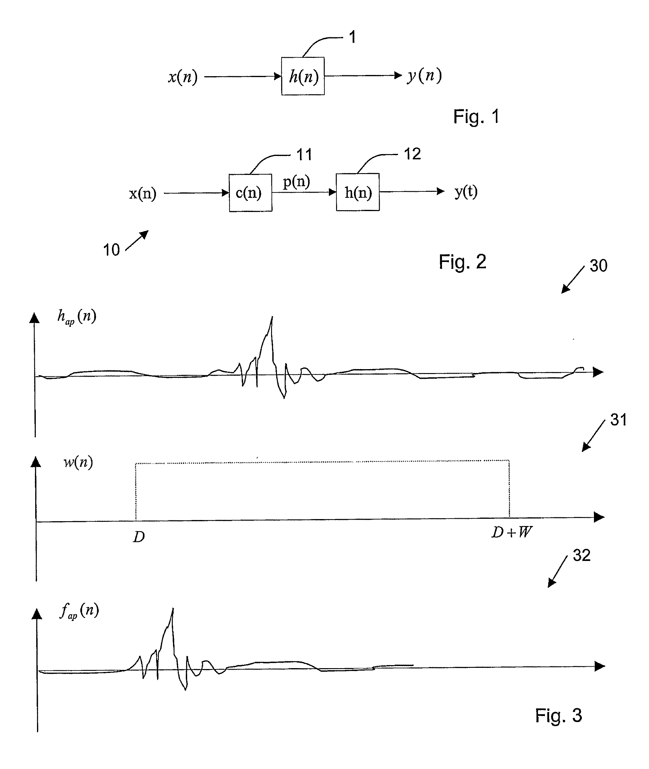
[0021] The purpose of a digital filter is to modify an input signal in a linear time-invariant fashion. Such a system is shown schematically in FIG. 1 wherein a discrete time (digital) input signal x(n), being convolved (or filtered) 1 by a filter described by h(n), to produce an output signal y(n).

[0022] Digital filtering can be represented in the time domain by equation (1). This relationship can also be shown as multiplication, if each signal is converted under the z-transform to form in Equation (2). y⁡(n)=∑k=0n⁢x⁡(k)⁢ ⁢h⁢ ⁢(n-k),n≥0(1)Y⁡(z)=X⁡(z)⁢H⁡(z)(2)

[0023] Where the z-transform and Inverse z-transform are defined as (3) and (4). X⁡(z)=∑n=-∞∞⁢x⁡(n)⁢ ⁢z-n(3)x⁡(n)=12⁢ ⁢π⁢ ⁢j⁢∮C⁢X⁡(z)⁢ ⁢zn-1⁢ⅆz(4)

[0024] As shown in FIG. 1, if a signal x(n) 10, passes through a filter c(n) 11 to produce an output p(n), it is possible to post equalise h(n) 12 the resulting response in order to perform some sort of modification to compensate f...


PUM


Abstract

A new method of designing digital filters for specific magnitude and phase requirements that minimises the filter's group-delay given arbitrary error tolerances is presented in this patent application. The method is extended to include optimising the original filter design based on the group-delay minimisation routine. A particular example that describes the linearisation of a filter channel under these conditions and given these constraints is shown. Embodiments may be applied to any digital filter design technique implemented in software, hardware, or a combination of both for applications such as equalisation or any area where filters are useful. The method disclosed is broadly applicable in the field of signal processing and may be used to advantage, for example in: channel equalisation, speaker and audio correction, echo-cancellation, control applications, digital audio broadcast, sonar and ultrasonics.

Description

CROSS-REFERENCE TO RELATED APPLICATIONS [0001] The present application is a continuation of pending International patent application PCT / AU2005 / 000677 filed on May 11, 2005 which designates the United States and claims priority from Australian patent application 2004902492 filed on May 12, 2004, the content of which is incorporated herein by reference.FIELD OF THE INVENTION [0002] The present invention relates to the field of digital signal processing and, in particular disclosed, a method and system for creating filter having predetermined group delays. BACKGROUND OF THE INVENTION [0003] Digital filtering of discrete-time sampled signals is used extensively in commercial applications such as compact disc players, digital stereo systems, digital mixing boards, digital speaker crossover networks, and in many other audio and non-audio signal processing applications. In order to make digital filters practical for real-time applications, they must have sufficiently low computational com...

Claims


Application Information

Patent Timeline
Patent Type & Authority Applications(United States)
IPC IPC(8): G06F17/10H03H17/00H03H17/06
CPCH03H2017/0072H03H17/06
Inventor GEORGE, BRETT DAVID
Owner CLARITY EQ
Why Eureka
Try Eureka