
Apparatus for sensing an output current in a communications device

a communication device and output current technology, applied in the field of power over ethernet (poe) devices, can solve the problems of reducing the accuracy of the current measurement system and the inability to accurately measure the curren

Inactive Publication Date: 2007-07-26
AVAGO TECH INT SALES PTE LTD
View PDF67 Cites 24 Cited by
  • Summary
  • Abstract
  • Description
  • Claims
  • Application Information

AI Technical Summary

Benefits of technology

The present invention relates to a current measurement system for a Power over Ethernet (PoE) device. The technical effect of the invention is to provide an accurate and efficient current measurement system for the PSE, which is the power source equipment in a PoE communications system. The current measurement system uses a detection IDAC and a classification circuit to distinguish between valid and invalid device signatures, open load, short circuit, and high voltage. The invention also includes a time division multiplexing scheme and an AC impedance measurement system for the PSE controller. The invention provides a more accurate and efficient current measurement system for the PSE, which is important for ensuring the safe and efficient operation of the PoE system.

Problems solved by technology

The small value of the parallel resistor reduces the ability to accurately measure the series resistor thereby diminishing the accuracy of the current measurement system.

Method used


Image

  • Apparatus for sensing an output current in a communications device
  • Apparatus for sensing an output current in a communications device
  • Apparatus for sensing an output current in a communications device

Examples


Embodiment Construction

[0037] The following detailed description of the present invention refers to the accompanying drawings that illustrate exemplary embodiments consistent with this invention. Other embodiments are possible, and modifications may be made to the embodiments within the spirit and scope of the invention. Therefore, the detailed description is not meant to limit the invention. Rather, the scope of the invention is defined by the appended claims.

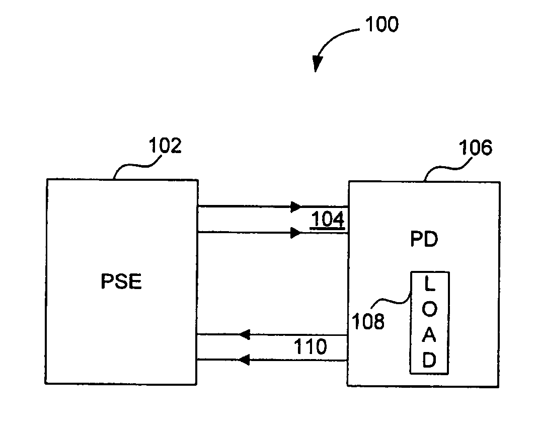
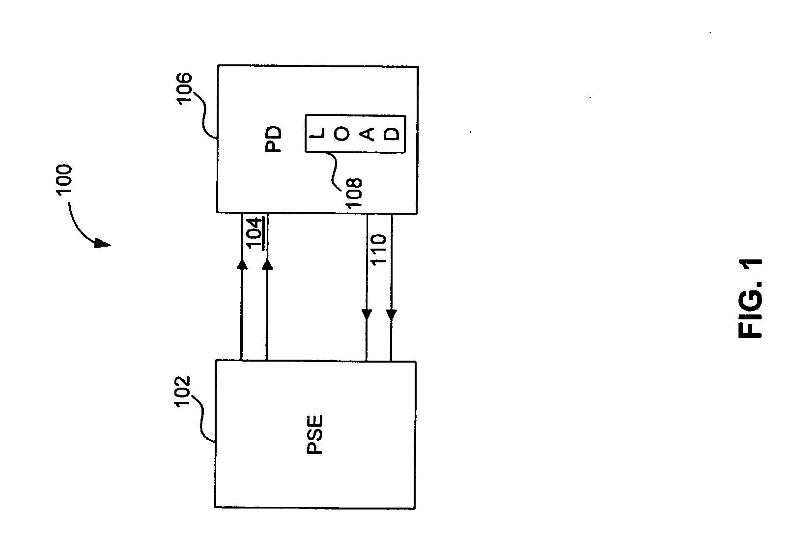
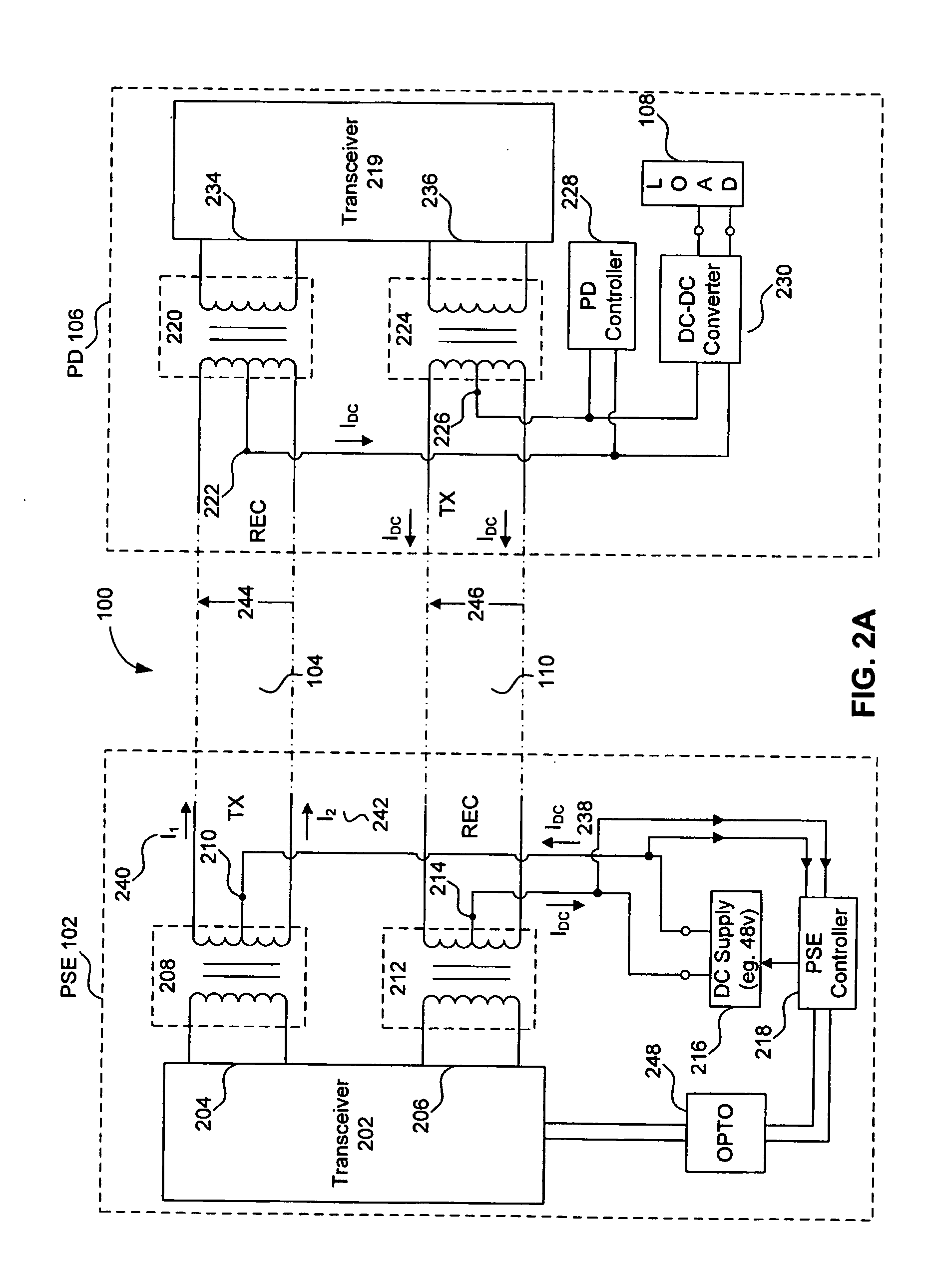
[0038]FIG. 1 illustrates a high level diagram of a conventional Power over Ethernet (PoE) system 100 that provides both DC power and data communications over a common data communications medium. Referring to FIG. 1, power source equipment 102 provides DC power over conductors 104, 110 to a powered device (PD) 106 having a representative electrical load 108. The PSE 102 and PD 106 also include data transceivers that operate according to a known communications standard, such as the IEEE Ethernet standard. More specifically, the PSE 102 includes a phy...


PUM


Abstract

Power over Ethernet (PoE) communication systems provide power and data communications over the same communications link, where a power source device (PSE) provides DC power (for example, 48 volts DC) to a powered device (PD). The DC power is transmitted simultaneously over the same communications medium with the high speed data from one node to the other node. The PSE typically includes a controller that controls the DC power provided to the PD at the second node of the communications link. The PSE controller measures the voltage, current, and temperature of the outgoing and incoming DC supply lines to characterize the power requirements of the PD. The PSE controller includes a resistorless switch to measure the current. The resistorless switch includes a sense transistor and a current mirror to allowing the PSE controller to calculate the current based upon a replica current.

Description

CROSS REFERENCE TO RELATED APPLICATIONS [0001] This patent application claims the benefit of U.S. Provisional Patent Application No. 60 / 758,984, filed Jan. 17, 2006, entitled “Power Over the Ethernet,” which is incorporated herein by reference in its entirety.BACKGROUND OF THE INVENTION [0002] 1. Field of the Invention [0003] The present invention generally relates to Power over Ethernet (PoE) devices, and more specifically to a power source equipment integrated circuit. [0004] 2. Related Art [0005] Ethernet communications provide high speed data communications over a communications link between two communications nodes that operates according the IEEE 802.3 Ethernet Standard. The communications medium between the two nodes can be twisted pair wires for Ethernet, or other types communications medium that are appropriate. Power over Ethernet (PoE) communication systems provide power and data communications over a common communications link. More specifically, a power source device (P...

Claims


Application Information

Patent Timeline
Patent Type & Authority Applications(United States)
IPC IPC(8): G06F13/00
CPCG06F1/266H04B3/44H04L12/10Y10S370/91H04L25/02G06F1/26H04L12/40045
Inventor VORENKAMP, PIETER
Owner AVAGO TECH INT SALES PTE LTD
Learn More