Control device for hydraulic actuator in piston

a control device and hydraulic actuator technology, which is applied in the direction of engine controllers, machines/engines, mechanical apparatus, etc., can solve the problems of short pressure reduction time period of hydraulic actuator hydraulic chamber, short pressure reduction time period of hydraulic actuator, and inability to operate normally. , to achieve the effect of improving the output performance of the engin

Inactive Publication Date: 2007-08-02
HONDA MOTOR CO LTD
View PDF0 Cites 28 Cited by
  • Summary
  • Abstract
  • Description
  • Claims
  • Application Information

AI Technical Summary

Benefits of technology

[0019] With the fifth embodiment of the present invention, the variable compression ratio device is precisely operated by cooperation of the main switching valve and the auxiliary switching v

Problems solved by technology

However, this time period of the reduced pressurize is too short for the hydraulic actuator to return to the non-operating state.
In addition, the pressure by the upward inertia force becomes larger as the engine rotational speed becomes higher

Method used


Image

  • Control device for hydraulic actuator in piston
  • Control device for hydraulic actuator in piston
  • Control device for hydraulic actuator in piston

Examples


first embodiment

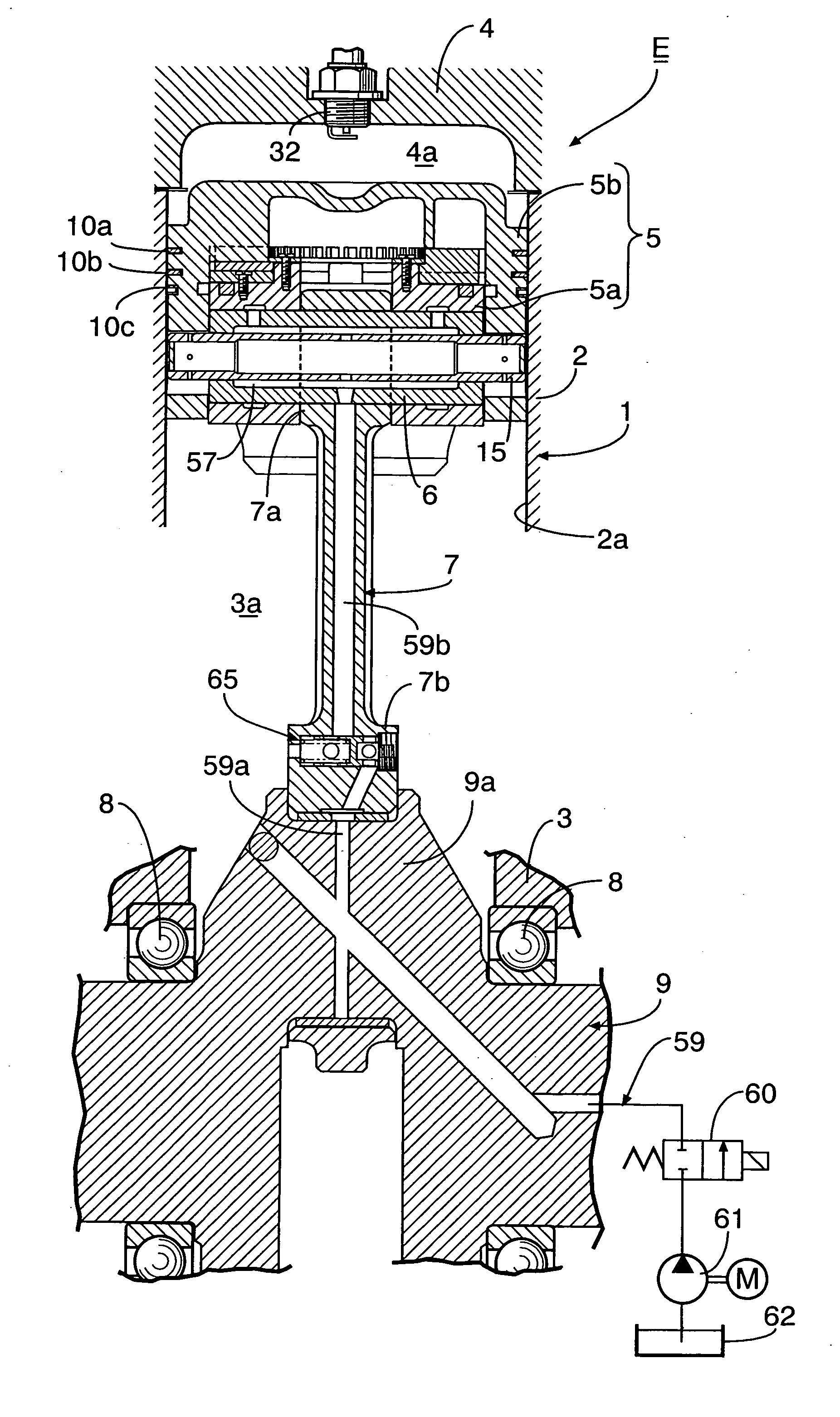
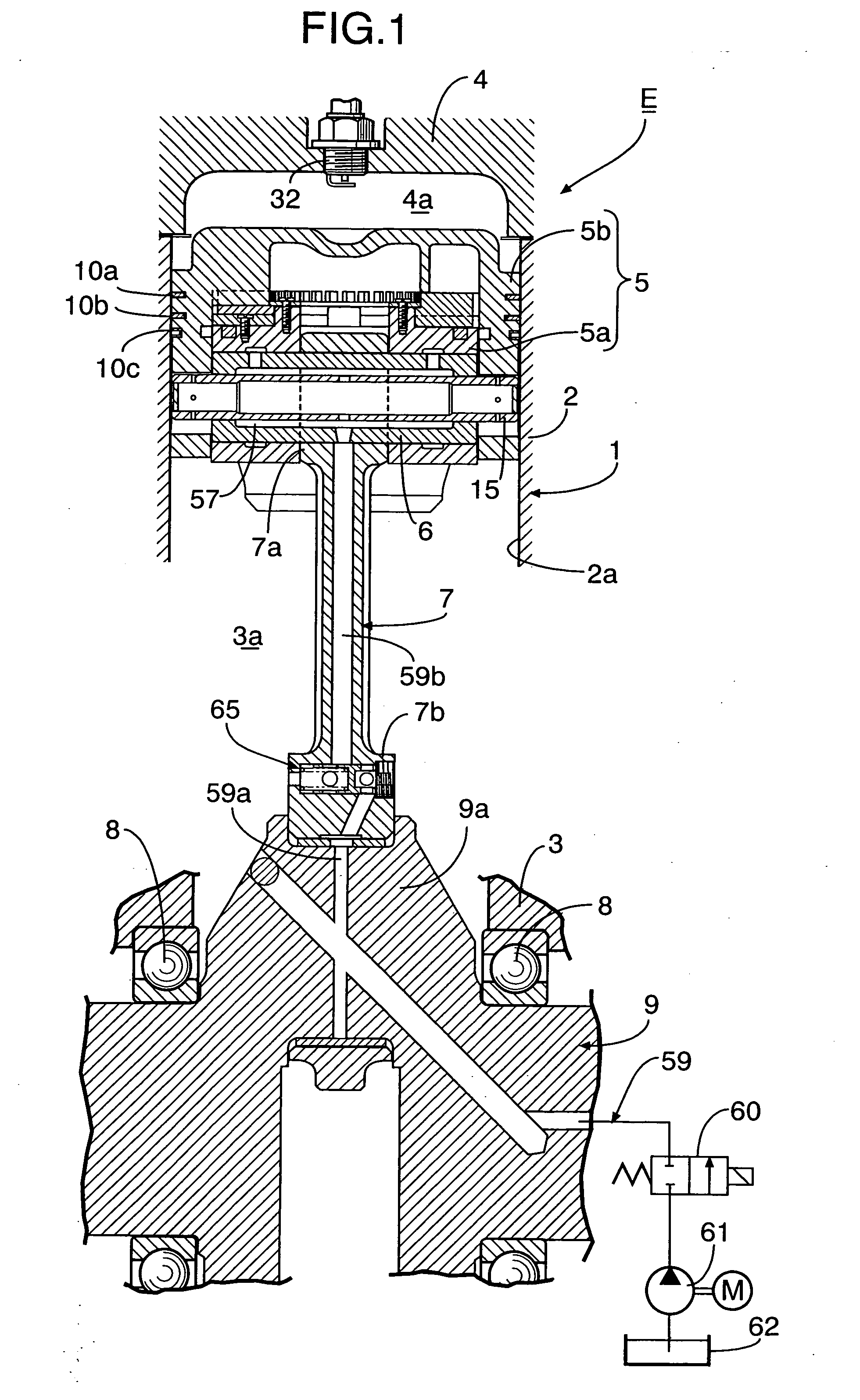
[0042] the present invention will be described with reference to FIGS. 1 to 18. In FIGS. 1 and 5, an engine body 1 of an internal combustion engine E includes a cylinder block 2 having a cylinder bore 2a, a crankcase 3 which is connected to a lower end of the cylinder block 2 and a cylinder head 4 which has a pent roof type combustion chamber 4a connected to an upper end of the cylinder bore 2a and which is connected to an upper end of the cylinder block 2. Threadedly fitted to the cylinder head 4 are an intake valve 31i and an exhaust valve 31e that open and close an intake port 30i and an exhaust port 30e which are opened in a ceiling surface of the combustion chamber 4a. An ignition plug 32 with electrodes is provided that faces a central portion of the combustion chamber 4a.

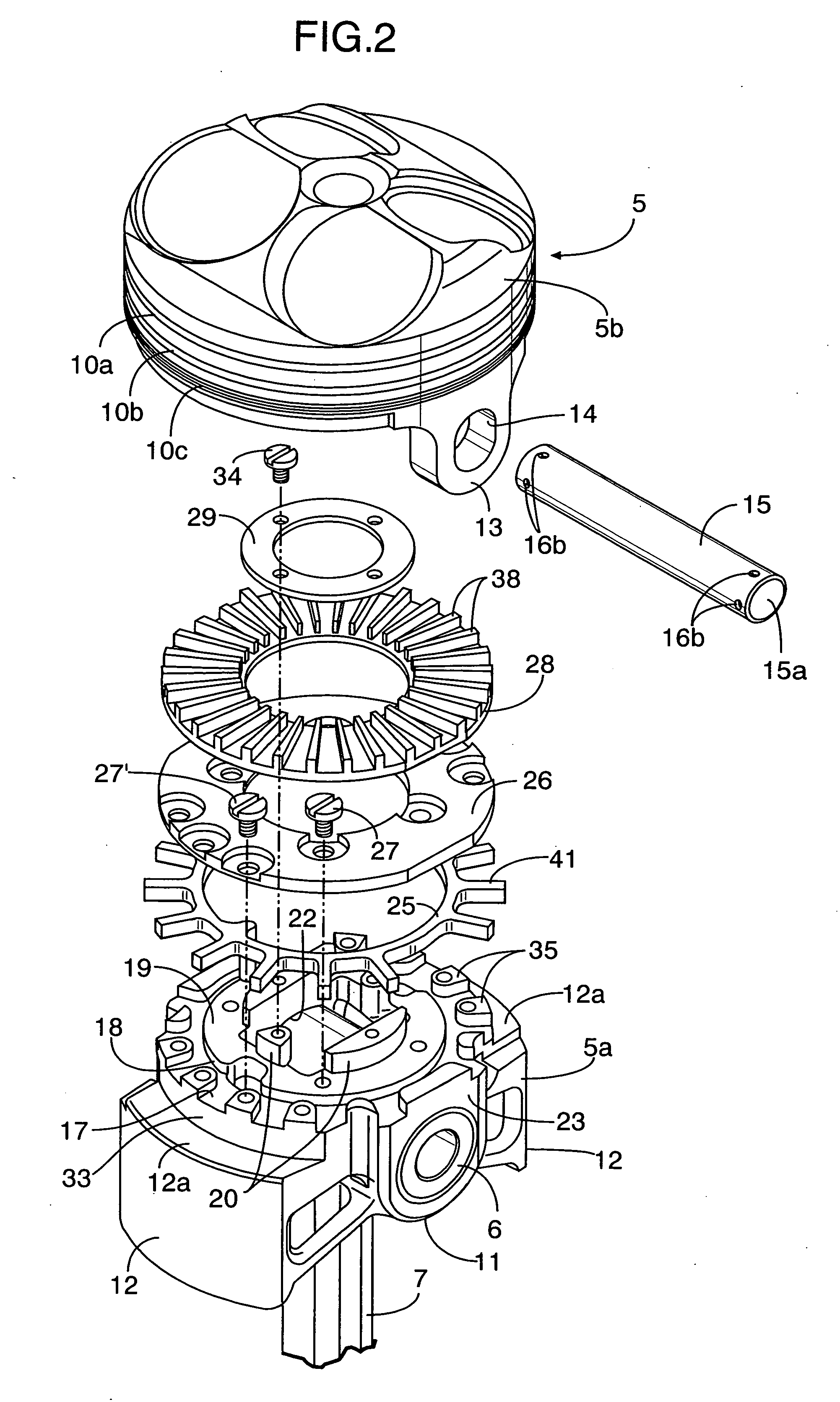
[0043] A small end portion 7a of a connecting rod 7 is connected via a piston pin 6 to a piston 5 which is slidably fitted in the cylinder bore 2a. A large end portion 7b of the connecting rod 7 is connected...


PUM


Abstract

In a control device for a hydraulic actuator, one end of an oil passage that is provided through a connecting rod, a crankshaft and a crankcase supporting the crankshaft is connected to a hydraulic chamber of a hydraulic actuator provided in a piston connected to the crankshaft via the connecting rod with the other end of the oil passage being connected to an oil reservoir and a hydraulic pressure source via a main switching valve. An auxiliary switching valve is provided in the connecting rod. The auxiliary switching valve causes a downstream side of the oil passage that leads to the hydraulic chamber to open into the crankcase when the main switching valve allows the oil passage to communicate with the oil reservoir.

Description

CROSS-REFERENCE TO RELATED APPLICATION [0001] The present application claims priority under 35 USC 119 to Japanese Patent Application No. 2005-379082 filed on Dec. 28, 2005 the entire contents of which are hereby incorporated by reference. BACKGROUND OF THE INVENTION [0002] 1. Field of the Invention [0003] The present invention relates to an improvement of a control device for a hydraulic actuator in a piston, in which one end of an oil passage that is provided through a connecting rod, a crankshaft and a crankcase supporting the crankshaft is connected to a hydraulic chamber of a hydraulic actuator provided in a piston connected to the crankshaft via the connecting rod with the other end of the oil passage is connected to an oil reservoir and a hydraulic pressure source via a main switching valve. The main switching valve moves between a first switching position which allows the oil passage to communicate with the oil reservoir, and a second switching position which allows the hydr...

Claims


Application Information

Patent Timeline
IPC IPC(8): F02B75/04F02D15/02
CPCF02D15/02F02B75/044
Inventor TAKAHASHI, KAZUTAKAITO, YUUICHIKONDO, TAKASHI
Owner HONDA MOTOR CO LTD
Why Eureka
Try Eureka