
Three-way, two-position in-tube solenoid gas valve assembly

a solenoid valve and in-tube technology, applied in the field of solenoid valves, can solve the problems of increasing the inapplicability of solenoid valves in the high-pressure pneumatic system, and the increase in the demand for high-pressure gas in the pneumatic system

Inactive Publication Date: 2007-08-02
WANG WEI CHING +2
View PDF4 Cites 6 Cited by
  • Summary
  • Abstract
  • Description
  • Claims
  • Application Information

AI Technical Summary

Benefits of technology

[0003] Accordingly, it is an object of the present invention to provide a three-way, two-position in-tube solenoid gas valve assembly of the above mentioned general type which avoids the disadvantages of the prior arts.
[0005] It is also an object of the present invention to provide a three-way, two-position in-tube solenoid gas valve assembly that will virtually act instantaneously.
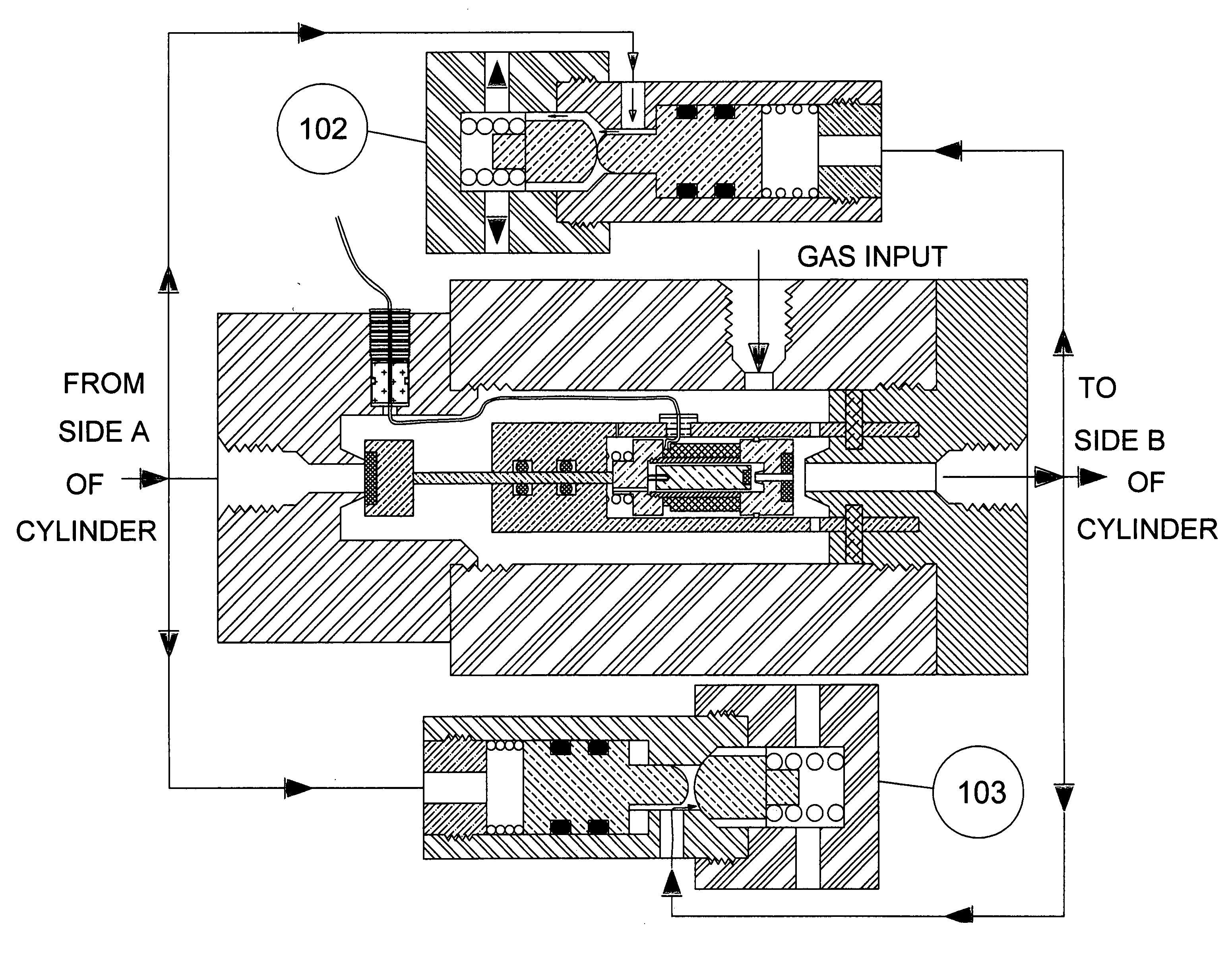
[0009] A gas release valve comprises of a body piston and a cap piston, which are actuated by gas pressure from the outlets of the modified in-tube solenoid gas valve. The gas release valve helps the residue gas in the pneumatic system to escape.

Problems solved by technology

Comparing to hydraulics, pneumatics systems often have many disadvantages in different fields of applications in the present market.
Since the hydraulic power system requires more complex conversion equipment which is not suitable for the portable or movable applications; hence, the demand of high pressure gas in pneumatic system is increasing.
However, those solenoid valves are not applicable in high pressure pneumatic system.
Due to the inefficiency of the manual operation processes of cleaning and de-burring, the quality control of production of valve is dismal.

Method used


Image

  • Three-way, two-position in-tube solenoid gas valve assembly
  • Three-way, two-position in-tube solenoid gas valve assembly
  • Three-way, two-position in-tube solenoid gas valve assembly

Examples


Embodiment Construction

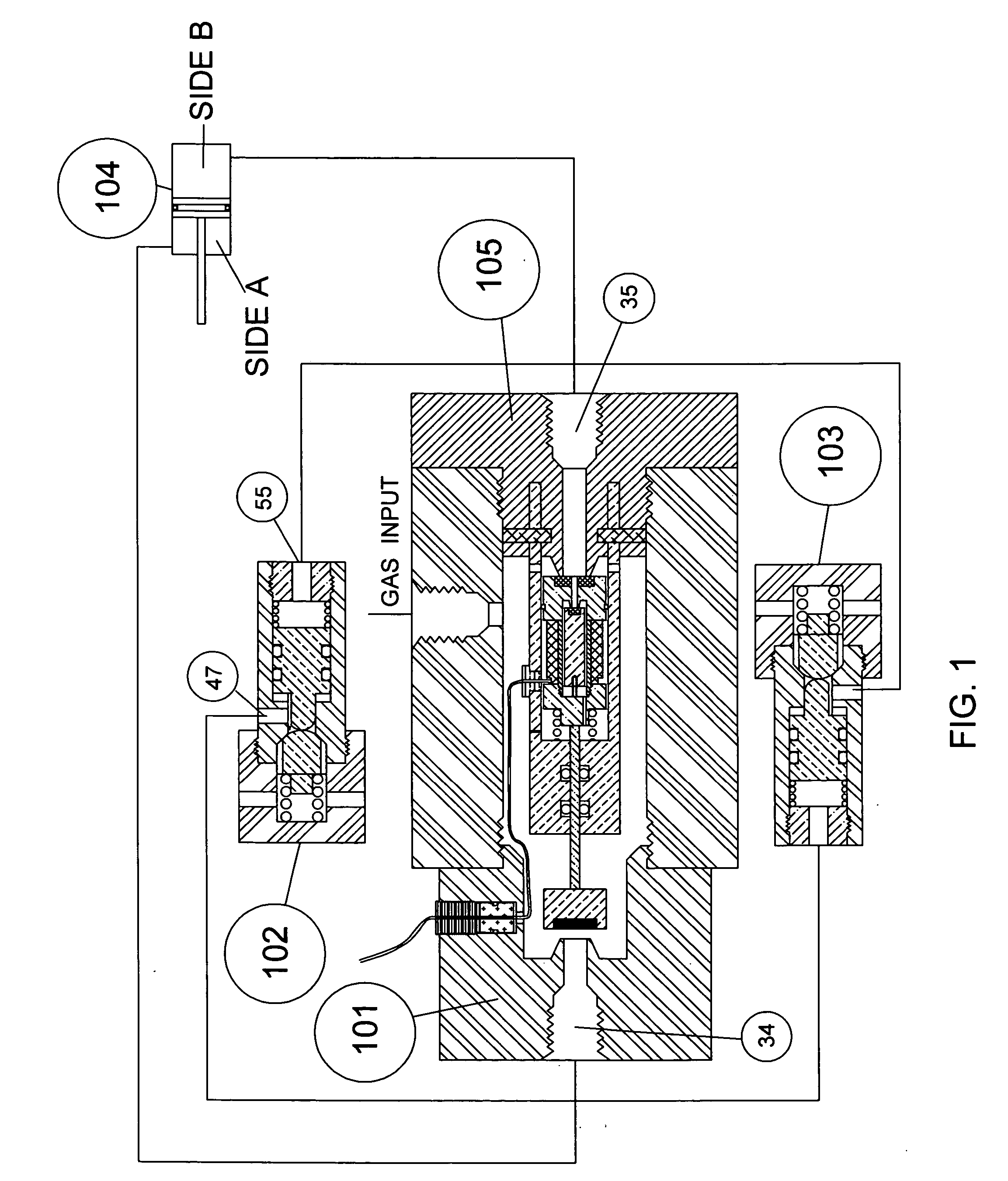
[0018] Attention is first directed to FIG. 1, which shows a schematic diagram of a pneumatic system 104 having sides A and B is attached to a three-way, two-position, in-tube solenoid valve assembly, which consists of a modified in-tube solenoid gas valve 101 and two identical gas release valves 102 and 103. Side A of cylinder 104 is connected to exiting port 34 of the modified in-tube solenoid gas valve 101, port 47 of gas release valve 102 and port 55 of gas release valve 103. Side B of cylinder 104 is connected to the existing port 35 of the modified in-tube solenoid gas valve 101, port 55 of gas release valve 102 and port 47 of gas release valve 103.

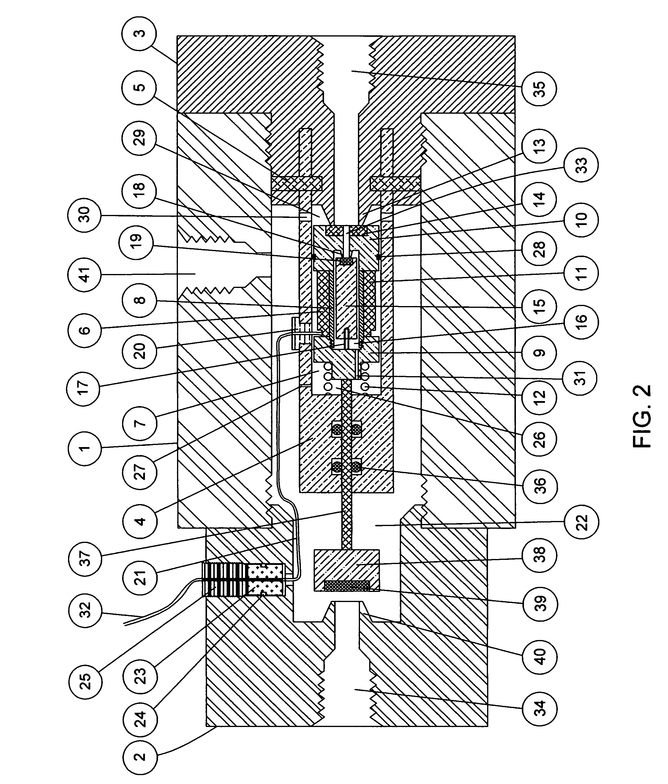
[0019]FIG. 2 shows a section view of a modified in-tube solenoid gas valve. The valve tube 1 has a hollow hole with internal thread at both ends to accept both outlet fittings 2 and 3. Both fittings have an exiting port 34 and 35 with internal threads for connecting adaptive fittings of piping system. A gas input port 41 is located ...


PUM


Abstract

A new three-way, two-position in-tube solenoid gas valve assembly comprises a modified in-tube solenoid gas valve and a pair of gas release valves is designed to control pneumatic systems. The modified in-tube solenoid gas valve is a modification based on the previous invention by Wang et al., U.S. Ser. No. 10 / 924,789. The new modifications are first adding a rod-piston assembly onto the solenoid assembly, a new inlet was added to the valve tube and two outlet fittings were also added. With these modifications, the systems can now work with two directions of gas flows, which is important to control pneumatic systems. To be able to control pneumatic systems properly, two gas release valves are included as part of the assembly. The goal of these two gas release valves is to be able to release gas from pneumatic quickly and completely. These gas release valves are operated based on two compression springs and through gas inputs into the valves. The operations of the gas releases valves are simultaneously while one opens the other closes. The opening and the closing of the gas release valve depends on the state of the modified solenoid gas valve.

Description

FIELD OF THE INVENTION [0001] The primary application field of the invention relates to a solenoid valve and more particularly, to a three-way, two-position in-tube solenoid gas valve assembly to switch the gas passage in high pressure pneumatic system. BACKGROUND OF THE INVENTION [0002] Comparing to hydraulics, pneumatics systems often have many disadvantages in different fields of applications in the present market. For example, the typical pressure range of hydraulic system is from 500 to 5,000 psig while a typical pneumatic system, the common pressure range from 0 to 80 psig, sometimes up to 1,000 psig for some special applications. However, there are reasons people would prefer a pneumatic system to a hydraulic one because of the simplicity of a pneumatic system which provides a low cost. I addition, it can be easily adapted to current applications and it is less sensitive to environmental factors. Since the hydraulic power system requires more complex conversion equipment whic...

Claims


Application Information

Patent Timeline
IPC IPC(8): F16K31/06
CPCF15B13/0405Y10T137/87209Y10T137/86887Y10T137/86622Y10T137/86895Y10T137/87241
Inventor WANG, WEI-CHINGWANG, CHIA-PINGWANG, YU-CHING
Owner WANG WEI CHING
Learn More