
Liquid jetting head and liquid jetting apparatus

a liquid jetting head and liquid technology, applied in the direction of printing, inking apparatus, etc., can solve the problems of reducing printing speed, difficult to change driving condition to a large degree, and inability to control the amount of ink droplets without changing, so as to reduce manufacturing costs and facilitate manufacturing.

Inactive Publication Date: 2007-08-02
KONICA MINOLTA INC
View PDF1 Cites 14 Cited by
  • Summary
  • Abstract
  • Description
  • Claims
  • Application Information

AI Technical Summary

Benefits of technology

[0010]The invention has been achieved in view of the above problems, and an object of the present invention is to provide a liquid droplet jetting head and liquid droplet jetting apparatus where manufacturing is easy, the manufacturing cost can be reduced, and an amount of ink droplet can be varied in a multi-step without causing side effects such as a fluctuation of a flying speed of the ink droplet.

Problems solved by technology

However, usually, it was difficult to change the driving condition to a large degree so as to change a diameter of the ink droplet.
In particular, it was not possible to control the amount of ink droplet without changing a speed of the ink droplet.
In this method, a variable contrast image can be outputted consistently in a sufficiently high quality though, a decrease of a printing speed is caused since the ink jetting is carried out the plurality of times.
In this case, though a level of contrast increase, there is a problem that a cost of manufacturing the head increases as the recording head becomes large.

Method used


Image

  • Liquid jetting head and liquid jetting apparatus
  • Liquid jetting head and liquid jetting apparatus
  • Liquid jetting head and liquid jetting apparatus

Examples


embodiment

[0110]Present Invention

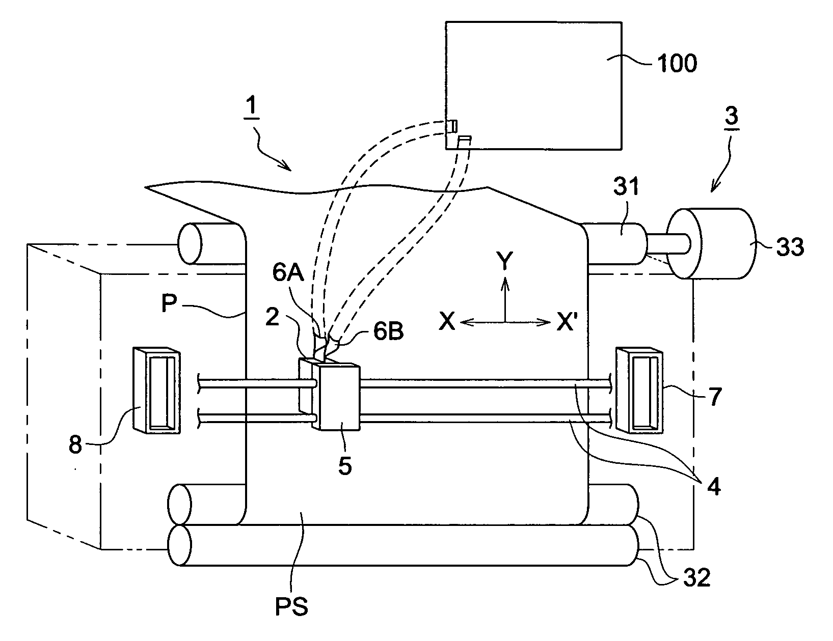
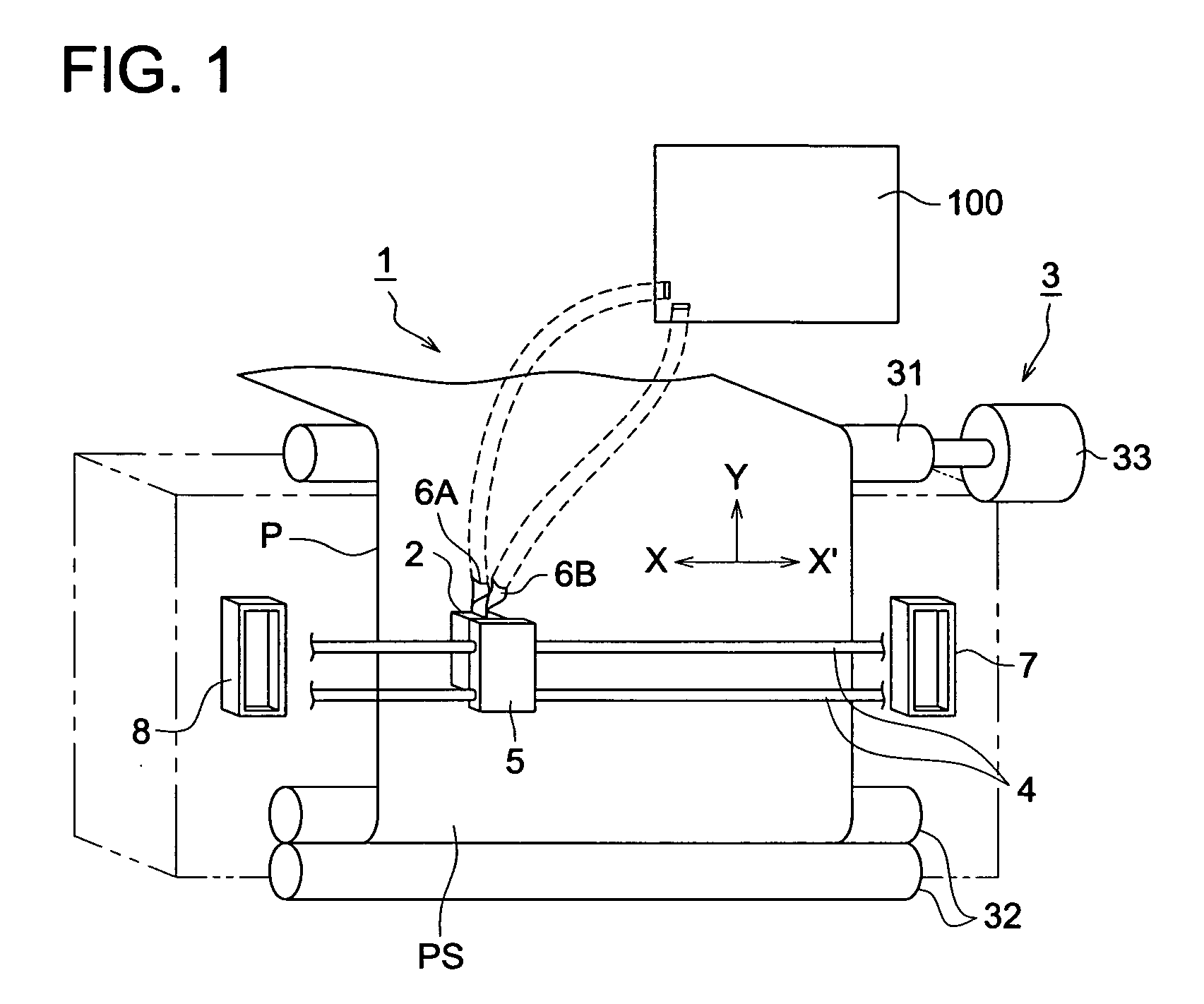
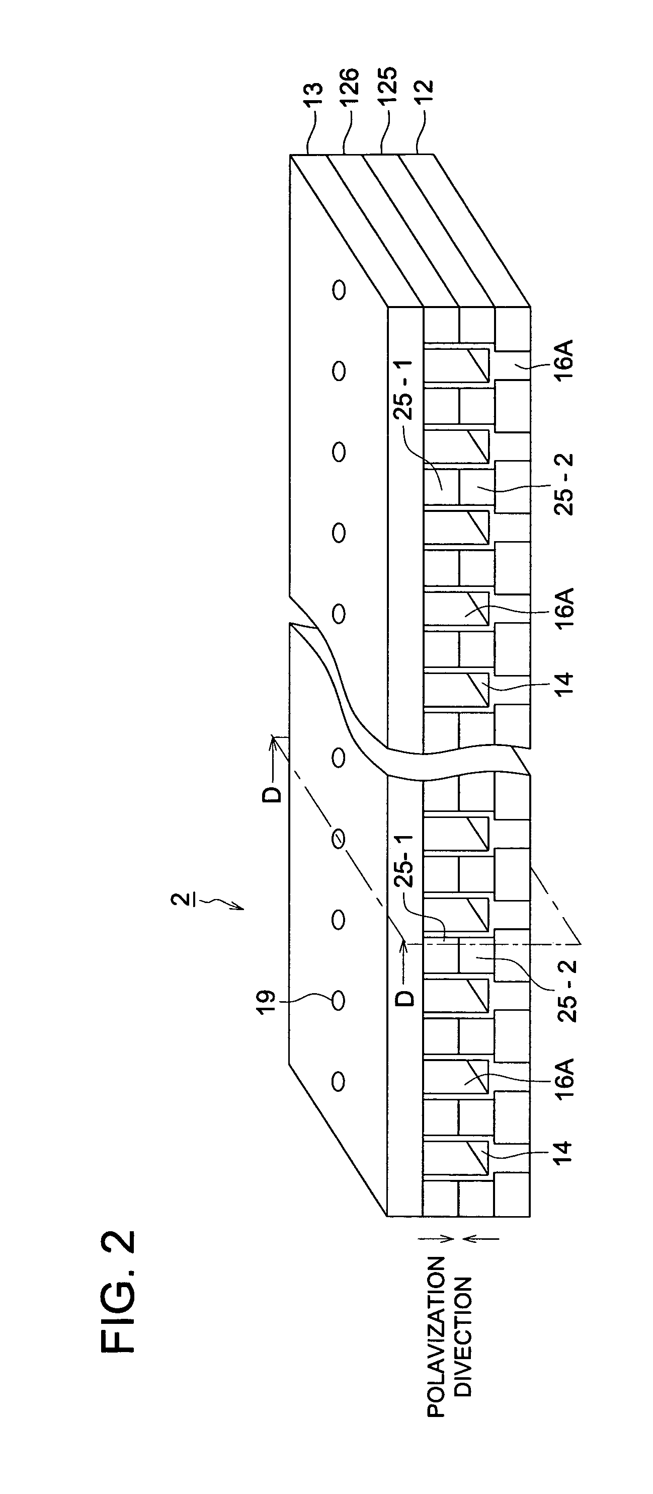
[0111]On the shear mode type head (number of nozzles: 256) shown in FIG. 3, three cycle driving was conducted in the following conditions for only each of flow paths 14A, which are split into 3 groups, by using the driving signal (the voltage and the pulse width are shown in Table 1 (a)) show in FIG. 7. Also three cycle driving was conducted in the following conditions for each of flow paths 14A and 14B which are split into 3 groups, by using the driving signal (the voltage and the pulse width are shown in Table 1) shown in FIG. 9.

[0112]Meanwhile, AL of the head was 7.4 μsec in case only 14 A was driven and 7.8 μsec in case both 14A and 14B are driven.

[0113]A water-soluble dye-based ink is use as the ink.

[0114]In this experiment, a polarized PZT is used as piezoelectric element substrate 125 and 126 and an aluminum nitride substrate (AIN-BN of Sumitomo ceramic co., ltd.) is used as lower wall 12. Also, as nozzle plate 13a forming upper wall 13, polyimide resin...


PUM


Abstract

A liquid droplet jetting head, having: a plurality of dividing walls to divide a plurality of flow channels, wherein at least a portion of the dividing wall is formed with a piezoelectric element; a flow path having a rectangular tubular from formed by an upper wall to close an upper surface of the flow path along an array direction of the plurality of the flow paths, and a lower wall to close a lower surface of the flow path; a nozzle to jet liquid in the flow path as the liquid droplet; and two driving electrodes formed independently on each wall surface of the dividing wall in a longitudinal direction of the flow path having the rectangular tubular form, wherein the nozzle is formed on either the upper wall or the lower wall.

Description

[0001]This application is based on Japanese Patent Application No. 2006-025538 filed on Feb. 2, 2006, in Japanese Patent Office, the entire content of which is hereby incorporated by reference.BACKGROUND OF THE INVENTION[0002]The present invention relates to a liquid droplet jetting head to jet liquid from a nozzle and a liquid droplet jetting apparatus.[0003]In a liquid jetting head to jet a liquid droplet from a nozzle such as an inkjet head (hereafter may called just head) to record an image by using a minimal ink droplet, a pressure generating device applies a pressure to a pressure generating chamber to jet the ink droplet from the nozzle so as to land the ink droplet on a recording medium like a recording sheet.[0004]Conventionally, so called shear mode type ink jet recording head (hereinafter also called shearing mode head) has been known in which an actuator substrate is configured by forming a number of channels on a polarized piezoelectric element, a cover plate is bonded ...

Claims


Application Information

Patent Timeline
Patent Type & Authority Applications(United States)
IPC IPC(8): B41J2/175
CPCB41J2/04543B41J2/04581B41J2/04588B41J2202/10B41J2002/14419B41J2002/14491B41J2/04596
Inventor TAKEUCHI, YOSHIO
Owner KONICA MINOLTA INC
Learn More