Electrostatic actuator, liquid droplet ejection head, liquid droplet ejection device and electrostatic driving device as well as methods of manufacturing them

a technology of electrostatic driving device and actuator, which is applied in the field of electrostatic actuator, can solve the problems of poor response, small effect, and inability to reach the portion of the fixed electrode having a long gap length, and achieve excellent operation performan

Inactive Publication Date: 2007-08-02
SEIKO EPSON CORP
View PDF0 Cites 4 Cited by
  • Summary
  • Abstract
  • Description
  • Claims
  • Application Information

AI Technical Summary

Benefits of technology

[0040]According to the aspect of the present invention, since the method of manufacturing the electrostatic actuator is appl

Problems solved by technology

However, the effect of it cannot reach the portion of the fixed electrode having a long gap length.
As a result, a drive voltage necessary to cause the portion having the long gap length to be abutted cannot help being applied between the electrodes, and thus even if the drive voltage is reduced, the effect of

Method used


Image

  • Electrostatic actuator, liquid droplet ejection head, liquid droplet ejection device and electrostatic driving device as well as methods of manufacturing them
  • Electrostatic actuator, liquid droplet ejection head, liquid droplet ejection device and electrostatic driving device as well as methods of manufacturing them
  • Electrostatic actuator, liquid droplet ejection head, liquid droplet ejection device and electrostatic driving device as well as methods of manufacturing them

Examples


embodiment 1

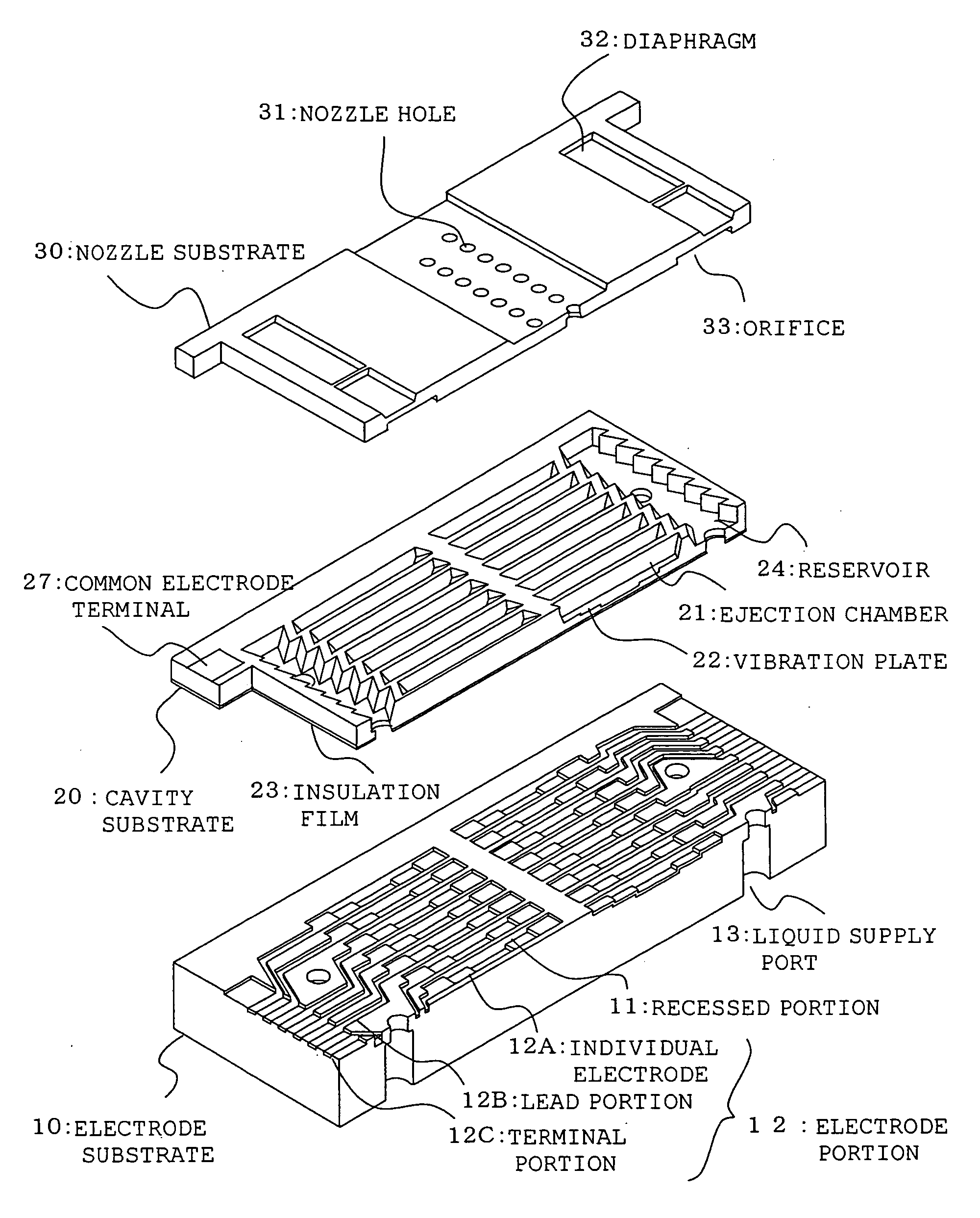
[0054]FIG. 1 is view showing a liquid droplet ejection head according to an embodiment 1 of the present invention by exploding it. FIG. 1 partly shows the liquid droplet ejection head. In the embodiment, a face inject type liquid droplet ejection head will be explained as a typical device using an electrostatic actuator driven by an electrostatic system. (Note that, to make illustrated components more understandable, the relation among the sizes of respective components may be different from an actual relation in the following figures including FIG. 1. Further, in the following explanation, it is assumed that upper sides means the upper side of the figures and lower sides means the lower sides of the figures.)

[0055]As shown in FIG. 1, the liquid droplet ejection head according to the embodiment is arranged by sequentially laminating three substrates, that is, an electrode substrate 10, a cavity substrate 20, and a nozzle substrate 30 from a lower side. In the embodiment, the electro...

embodiment 2

[0099]Portions A to G of FIG. 10 are views showing steps for forming a boron diffused layer acting as a vibration plate 22 according to an embodiment 2. In the embodiment 1 described above, boron is diffused several times into, a thickest portion and the like depending on the number of stepped portions. However, a method of the second embodiment is different from that of the first embodiment in that born is diffused into a desired position with a desired thickness (depth) by being diffused once. Since steps shown in parts A and B of FIG. 10 are the same as the first embodiment, explanation thereof is omitted.

[0100]In the portion of the silicon substrate 80, to which a boron diffused layer is formed thickest, silicon is exposed. Then, the silicon substrate 80 is put into a vertical furnace with the surface thereof, on which the boron diffused layer is to be formed, facing a solid boron diffusion source mainly composed of B2O3, and boron is diffused into the silicon exposed portion of...

embodiment 3

[0104]FIG. 11 is an outside appearance view of a liquid droplet ejection device using a liquid droplet ejection head manufactured in the embodiment described above. Further,

[0105]FIG. 12 is a view showing an example of main means for constituting the liquid droplet ejection device. An object of the liquid droplet ejection device of FIGS. 11 and 12 is to carry out print by a liquid droplet ejection system (inkjet system). Further, the liquid droplet ejection device is a so-called serial device. In FIG. 12, the liquid droplet ejection device is mainly composed of a drum 101 for supporting a print sheet 100 as a to-be-printed matter, and a liquid droplet ejection head 102 for ejecting ink to the print sheet 100 and carrying out recording. Further, although not shown, the liquid droplet ejection device also includes an ink supply means for supplying ink to the liquid droplet ejection head 102. The print sheet 110 is held by being pressed against the drum 101 by a sheet press roller 103 ...


PUM


Abstract

An electrostatic actuator, a liquid droplet ejection head, and a liquid droplet ejection device which have a good response and are driven by a small drive voltage includes a vibration plate as a sheet-shaped movable electrode and an individual electrode acting as a rectangular fixed electrode confronting the vibration plate and having stepped portions or an inclined portion in a long side direction with respect to the vibration plate, wherein the thickness of the vibration plate is reduced according to an order by which the vibration plate is made to abut against the individual electrode by electrostatic attracting force generated between the vibration plate and the individual electrode. Methods of manufacturing the above devices are also disclosed.

Description

[0001]The entire disclosure of Japanese Patent Application No. 2006-019067, filed Jan. 27, 2006, is expressly incorporated by reference herein.BACKGROUND OF THE INVENTION[0002]1. Field of the Invention[0003]The present invention relates to an electrostatic actuator such as a droplet ejection head and the like for carrying out operation (drive) and the like by subjecting a movable portion to displacement and the like by force applied thereto in a micromachined device, to an electrostatic device such as a liquid droplet ejection device and the like using the actuator, and to methods of manufacturing them.[0004]2. Description of the Related Art[0005]A micromachining technology (MEMS Micro Electro Mechanical Systems) for forming a micro device and the like by processing, for example, silicon and the like has made rapid progress. As examples of a micromachined device formed by the micromachining technology, there are a liquid droplet ejection head (inkjet head) used in a recording (print...

Claims


Application Information

Patent Timeline
IPC IPC(8): B41J2/41
CPCB41J2002/14411B41J2/14314
Inventor KOMATSU, HIROSHIMATSUNO, YASUSHISANO, AKIRA
Owner SEIKO EPSON CORP
Why Eureka
Try Eureka