
Method And System For Improved Eye Protection Safety Of High Output Power Lumped Optical Amplifiers

a technology of optical amplifiers and lumped optical amplifiers, applied in the field of optical amplifiers, can solve the problems of high uncertainty in magnitude and characteristics of ass, strong back-reflection, etc., and achieve the effect of improving safety

Inactive Publication Date: 2007-08-02
II VI DELAWARE INC +1
View PDF7 Cites 13 Cited by
  • Summary
  • Abstract
  • Description
  • Claims
  • Application Information

AI Technical Summary

Benefits of technology

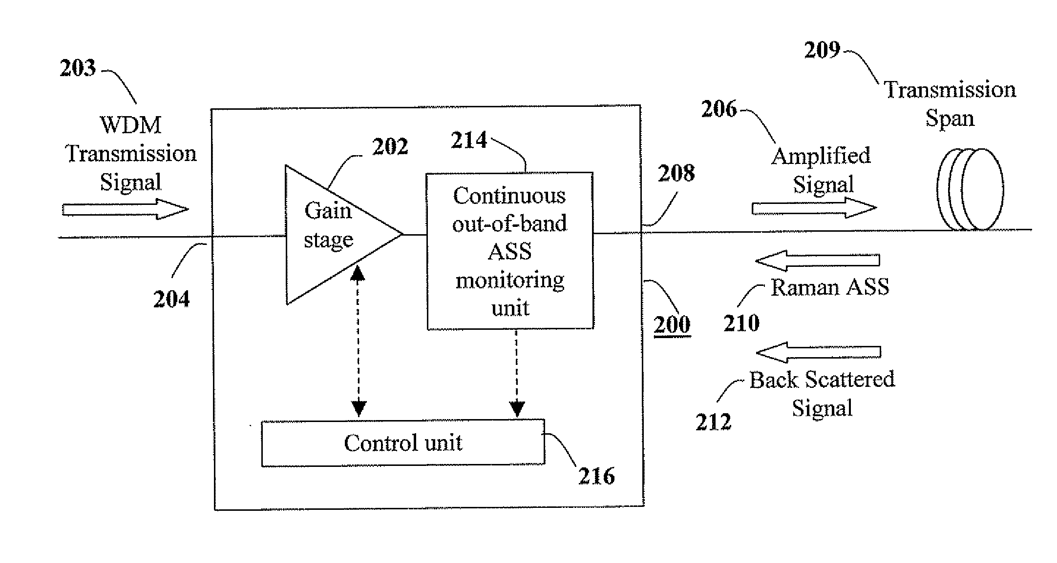
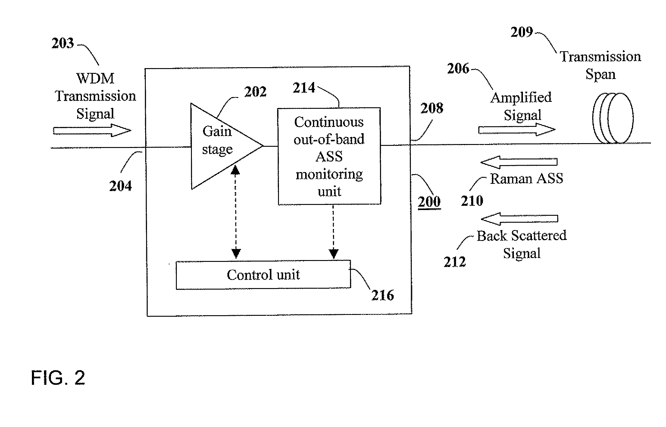
[0013] The present invention discloses an apparatus and method for providing improved safety during operation of a high output power optical amplifier by enabling the detection of an opening in the span connected to the output port of the amplifier, and for performing local and autonomous automatic shut-down upon the occurrence of such an open span event. The detection of the open span is based on continuous monitoring of the Raman ASS directed back to the output port of the amplifier, and created by the amplified signal as it propagates along the span. In the case of lumped optical amplifiers, where the amplifier output constitutes the amplified signal, the wavelength band of the monitored Raman ASS, as well as the calibration of the detection mechanism are tailored to account for the fact that the ASS is created by the amplified signal, which spectral composition may be unknown and unpredictable. Furthermore, allowance is provided for possible sharp changes in the Raman ASS (e.g. due to an Add / Drop event in the transmission link that changes the amplified signal), changes unrelated to an open span event, and which should therefore not cause unnecessary shut-down of the amplifier.
[0016] According to the present invention there is provided in an optical communication system, a method for enhancing eye-protection during a lumped optical amplifier operation, including the steps of amplifying an input signal of a predetermined wavelength band into an amplified signal transmitted through an output port of the amplifier to a communication network span; continuously monitoring an out-of-band Raman ASS power level related to the amplified signal; detecting in real-time when a change in the out-of-band Raman ASS power level signifies an open span; and, responsive to a result of the detection, reducing the power of the amplified signal or shutting down a gain stage of the amplifier, thereby obtaining enhanced eye-safety.

Problems solved by technology

The main problem with this method is that it works only when the open span is due to an open connector of type PC, which causes strong back-reflection.
Thus, while the high power amplified signal also generates Raman ASS in the transmission fiber (ASS which is directed back to the amplifier and can be detected), the magnitude and characteristics of this ASS are highly unpredictable and can change suddenly with time unrelated to an open span event.

Method used


Image

  • Method And System For Improved Eye Protection Safety Of High Output Power Lumped Optical Amplifiers
  • Method And System For Improved Eye Protection Safety Of High Output Power Lumped Optical Amplifiers
  • Method And System For Improved Eye Protection Safety Of High Output Power Lumped Optical Amplifiers

Examples


Embodiment Construction

[0032]FIG. 2 shows a lumped optical amplifier unit (e.g. an EDFA) 200 with an autonomous and local shut-down mechanism according to a preferred embodiment of the present invention. Amplifier unit 200 includes a gain stage 202 designed to amplify a WDM transmission signal 203 entering an input port 204 of the amplifier, creating an amplified signal 206 which exits an output port 208 of the amplifier. The input WDM signal may include one or more transmission channels located in a well defined transmission band, for example, the so-called C band located between 1525-1565 nm.

[0033] Gain stage 202 may be any type of optical amplifier gain stage known in the art, such as an EDFA gain stage, a semiconductor optical amplifier (SOA) gain stage, or a lumped (discrete) Raman amplifier gain stage. In addition, gain stage 202 may include more than one sub-stage (not shown), each of which may be any type of lumped optical amplifier gain stage, as well as various components between the sub-stages...


PUM


Abstract

A system and method for providing eye-safety protection during operation of a lumped optical amplifier. The method is based on monitoring of continuous out-of-band Raman amplified spontaneous scattering (ASS) created by the amplified signal in an optical communication network span coupled to an output port of the lumped optical amplifier. The system includes at least one gain stage for providing an amplified signal introduced into the span, a monitoring unit for performing the continuous Raman ASS monitoring, and a control unit operative to detect and analyze in real-time changes in the ASS power, and upon determination that such changes indicate an open span, to reduce the power of the amplified signal or shut down the gain stage.

Description

CROSS REFERENCE TO RELATED APPLICATIONS [0001] The present application is a continuation in part application of U.S. patent application Ser. No. 11 / 464,198, filed 13 Aug. 2006, which is a divisional application of U.S. patent application Ser. No. 11 / 001,055, filed 2 Dec. 2004, now U.S. Pat. No. 7,116,471 issued 3 Oct. 2006, all of which are hereby incorporated herein by reference.FIELD OF THE INVENTION [0002] The present invention relates generally to optical amplifiers used in fiber optics telecommunications systems. More particularly, the invention relates to high output power lumped optical amplifiers, and to methods and apparatuses for detecting and diagnosing faults in an optical communication system span that utilizes such amplifiers, in order to provide improved eye protection safety. BACKGROUND OF THE INVENTION [0003] Modem optical communication systems utilize optical amplifiers to amplify wavelength division multiplexed (WDM) signal channels as they are transmitted through...

Claims


Application Information

Patent Timeline
IPC IPC(8): H01S3/00
CPCH04B10/2931H04B10/0797
Inventor GHERA, URISHLIFER, ALEXMENASHE, DAVID
Owner II VI DELAWARE INC
Learn More