Method to make a perpendicular magnetic recording head with a side write shield

a magnetic recording head and side write shield technology, applied in the field of magnetic recording heads, can solve the problems of producing unwanted side-writing and much more obvious problems, and achieve the effect of high etch selectivity

Active Publication Date: 2007-08-02
HEADWAY TECH INC
View PDF16 Cites 102 Cited by
  • Summary
  • Abstract
  • Description
  • Claims
  • Application Information

AI Technical Summary

Benefits of technology

[0009] A second object of the present invention is to provide a method of forming such a pole structure for a perpendicular magnetic recording head in which side fringing of the magnetic field is significantly reduced.
[0011] A fourth object of the present invention is to provide a method of forming a perpendicular magnetic write head in which the effectiveness of the shielding allows the formation of a larger physical pole.
[0014] The objects of the present invention are realized by the formation of a self-aligned, three-way shielded PMR pole structure to be used within a PMR head wherein a pair of side shield are formed using reactive ion etching (RIE) or ion beam etching (IBE) together with a combination of gases selected to achieve high etch selectivity between a metal mask formed of Tantalum (Ta) and magnetic shield material formed of nickel-iron (NiFe) alloy. The selectively etched RIE (or IBE) process allows the dimensions of the mask opening to remain well defined while a beveled trench is formed within a layer of the aforesaid shield material, thereby separating the layer into two separate side shields whose sidewalls are the walls of the trench. A magnetic pole is then formed within the trench, the bevel angle of the magnetic pole being determined (ie., self-aligned) by the sidewall profile of the magnetic shield. Within the process, the metal mask advantageously also serves as a stopping layer for a chemical mechanical polishing (CMP) step. An upper shield is thereafter formed over the pole and side shields, creating the final three-way shielded structure of the present invention. The invention does not describe other elements of the write head, such as energizing coils, since these are well known in the prior art.

Problems solved by technology

A significant problem with magnetic pole structures that are currently used to produce perpendicular fields, is that the fields tend to exhibit significant lateral fringing, thereby producing unwanted side-writing (writing in adjacent tracks).
This problem is much more evident in the perpendicular writing head than in the longitudinal writing head, even when the perpendicular head is shielded laterally to contain the fringing fields.

Method used


Image

  • Method to make a perpendicular magnetic recording head with a side write shield
  • Method to make a perpendicular magnetic recording head with a side write shield
  • Method to make a perpendicular magnetic recording head with a side write shield

Examples


Embodiment Construction

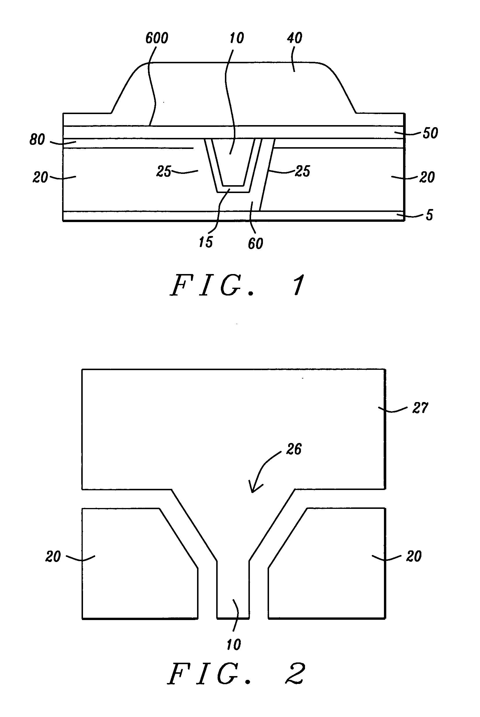
[0019] The preferred embodiment of the present invention is a three-way shielded pole structure for use within a perpendicular magnetic recording (PMR) head, in which the pole tip is formed and shaped within a trench between a pair of side shields and is thereafter covered from above by an upper shield. This three-way shield formation (two side shields, one upper shield) effectively eliminates side writing by the pole and, thereby, allows the formation of a physically larger pole while still maintaining desired track width definition.

[0020] Two views of the finished pole fabrication can be seen by referring to FIGS. 1 and 2. FIG. 1 is a schematic view through the ABS plane of the shielded PMR pole structure as it appears when formed as part of the PMR head (nominally called the “front” of the head) showing, in cross-section, a substrate (5), the beveled pole tip (10), two opposing side shields (20) laterally disposed about the pole tip and an upper shield (40) formed on a seed laye...


PUM

PropertyMeasurementUnit
thicknessaaaaaaaaaa
thicknessaaaaaaaaaa
thicknessaaaaaaaaaa

Abstract

A perpendicular magnetic recording (PMR) head is fabricated with a pole tip shielded laterally by a separated pair of side shields and shielded from above by an upper shield. The side shields are formed by a RIE process using specific gases applied to a shield layer through a masking layer formed of material that has a slower etch rate than the shield material. A masking layer of Ta, Ru / Ta, TaN or Ti, formed on a shield layer of NiFe and using RIE gases of CH3OH, CO or NH3 or their combinations, produces the desired result. The differential in etch rates maintains the opening dimension within the mask and allows the formation of a wedge-shaped trench within the shield layer that separates the layer into two shields. The pole tip is then plated within the trench and, being aligned by the trench, acquires the wedge-shaped cross-section of the trench. An upper shield is then formed above the side shields and pole.

Description

BACKGROUND OF THE INVENTION [0001] 1. Field of the Invention [0002] This invention relates generally to magnetic recording heads, particularly to perpendicular recording heads that produce their recording magnetic fields perpendicularly to the recording medium [0003] 2. Description of the Related Art [0004] The increasing need for high areal recording densities (up to 500 Gb / in2) is making the perpendicular magnetic recording head (PMR head) a replacement of choice for the longitudinal magnetic recording head (LMR head). By means of fringing magnetic fields that extend between two emerging pole pieces, longitudinal recording heads form small magnetic domains within the surface plane of the magnetic medium (hard disk). As recorded densities increase, these domains must correspondingly decrease in size, eventually permitting destabilizing thermal effects to become stronger than the magnetic interactions that tend to stabilize the domain formations. This occurrence is the so-called sup...

Claims


Application Information

Patent Timeline
Patent Type & Authority Applications(United States)
IPC IPC(8): G11B5/147
CPCG11B5/11G11B5/1278G11B5/3116G11B5/3146G11B5/315G11B5/3163Y10T29/49044Y10T29/49043Y10T29/49048Y10T29/49052Y10T29/49039Y10T29/49046Y10T29/49032
Inventor HAN, CHERNG-CHYILI, MINLIU, FENGLINLEE, JIUN-TING
Owner HEADWAY TECH INC
Why Eureka
Try Eureka