
Shaker

Active Publication Date: 2007-08-02
BERTHOLD TECH
View PDF10 Cites 26 Cited by
  • Summary
  • Abstract
  • Description
  • Claims
  • Application Information

AI Technical Summary

Benefits of technology

[0014] The present invention has as its object to provide a mixing apparatus for liquid substances that permits, with a simple design, an optimal thorough mixing of substances particularly in a microplate.
[0018] A particularly advantageous design provides that an appliance fan with external rotor motor is used as the motor, the external rotor of which is redesigned in such a way that it creates a rotating unbalance.
[0019] Supporting the support plate via bearing means that have a reset characteristic (e.g., spring characteristic) ensures that a central positioning of the support plate and, hence, of the microplate, is resumed after the motor is switched off, which ensures that the assumption may be made in controlling the positioning motors, that the positions of the sample containers relative to the drive mechanism of the X-Y horizontal displacement is [sic] not adversely affected by interposed mixing processes / shaking periods.
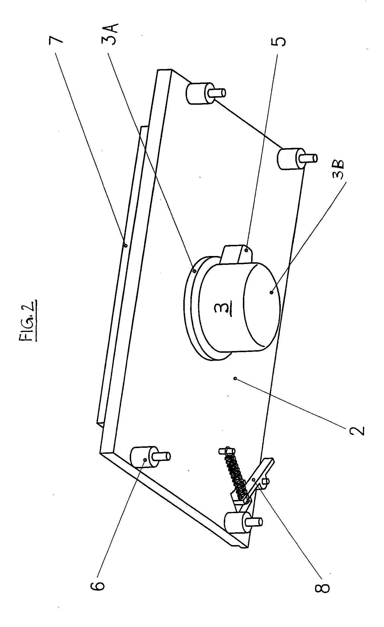
[0020] An additional, cost-effective design provides that the reset means being used as bearing elements are composed of commercially available types of vibration absorbers, which support the support plate with the motor perpendicularly to its plane on the base of the apparatus. The shaking movement that the motor imparts to the support plate due to the unbalance characteristic of said motor consequently leads to a lateral, directionally identical deflection of the at least three vibration absorbers, whose reset force superimposes itself over the effect of the motor and ensures the above-mentioned resuming of the central positioning of the microplate after the motor is switched off.
[0021] The added expense of installing the mixing apparatus in the case of a support plate for microplates that is moved within a measuring system is small, the mixing apparatus is space-saving, in particular, so that the integration (and optionally retrofitting) of the mixing apparatus, for example into a luminescence measuring system used in bioanalysis is simple.

Problems solved by technology

Since these motors, however, are designed for a very even and stepped operation, they are consequently not optimized for a generation of shaking movements of the microplates as it is required for a homogeneous mixing of the sample substances.
Moreover, using these positioning motors leads to significant wear of the components such as bearings and shafts, the “shaking amplitude” in the X and Y directions required for optimal thorough mixing is only partly adjustable, so that the functionality of this technology is limited.
This device is therefore neither suitable nor intended for integration into a measuring system for measuring luminescence or fluorescence, in which it must be ensured, for the manipulations (injections, measuring processes) that are performed during such measuring processes, that a uniquely reproducible position of the microplate is ensured after a mixing or shaking process as well.
In the case of this apparatus there is also no guarantee, in order to achieve conclusive and reproducible measuring results, that the various sample wells of the microplate will pass through the same planes of movement.
This proposed solution would therefore, in principle, permit an incorporation into a measuring system, however, due to the detail design of the drive units with eccentric ball bearings it is very complex, the latter drive units also requiring a certain amount of space in addition to the devices for x-y positioning and for displacement of the microplates into measuring or preparation positions.

Method used


Image

  • Shaker
  • Shaker
  • Shaker

Examples


Embodiment Construction

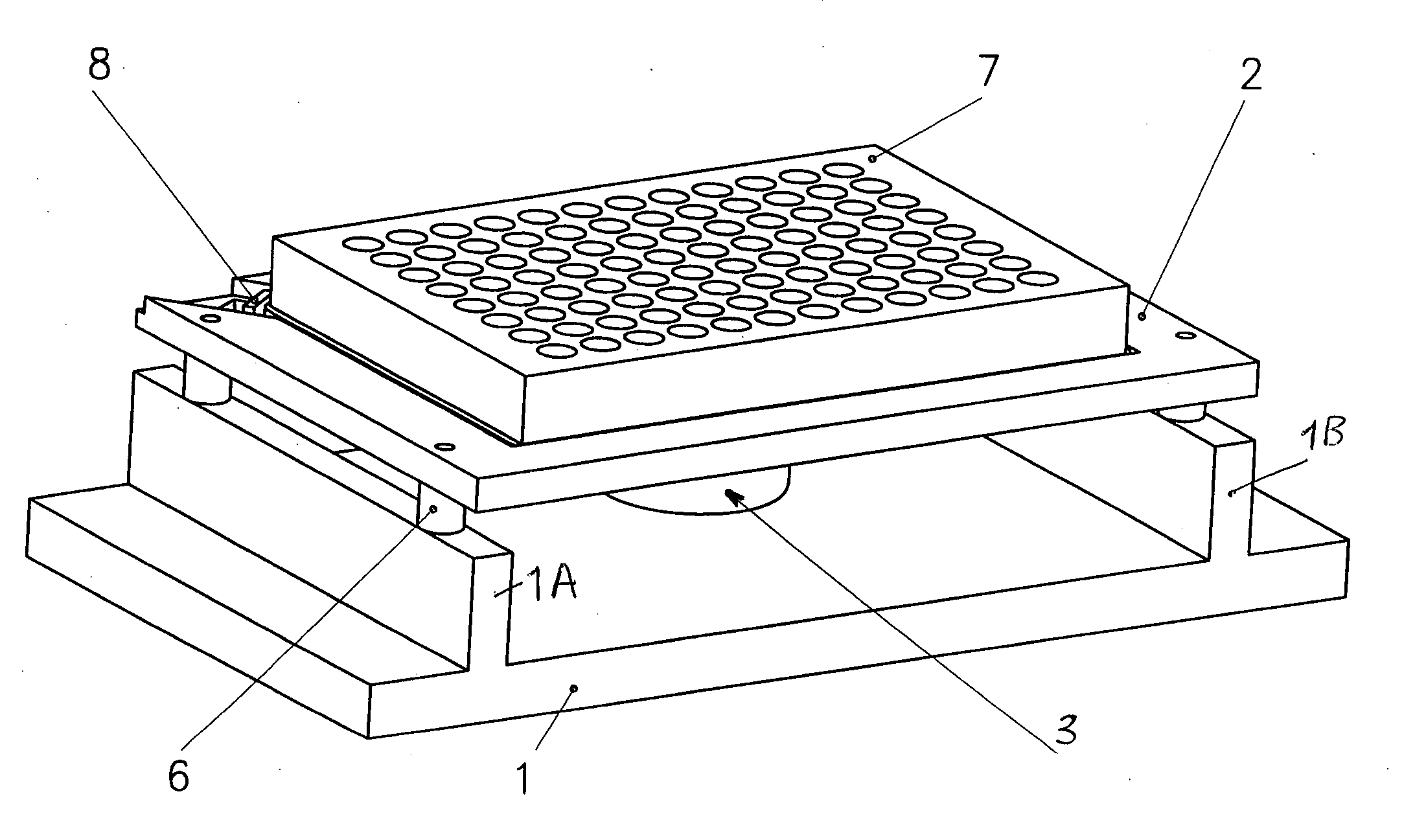
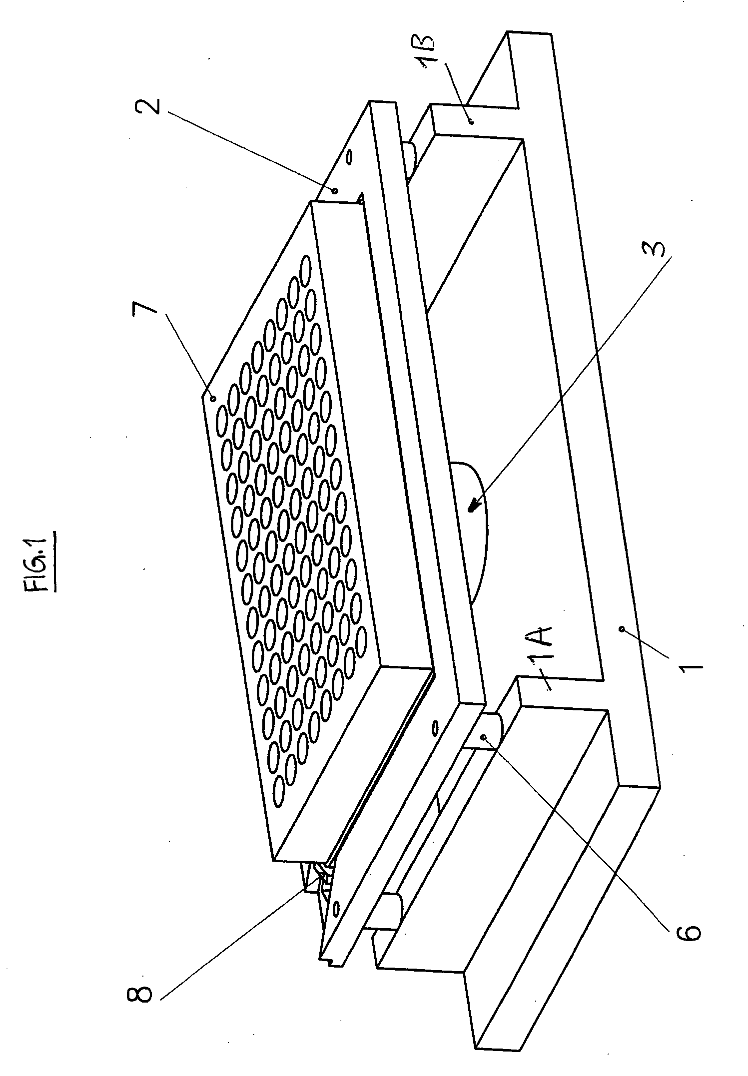
[0029] The measuring system consists of a base 1 having two ribs 1A, 1B extending parallel to its edges, which, in the depicted embodiment, each have two bearing elements 6 for supporting the support plate 2 for the microplate 7, the configuration of which will be explained in more detail further below.

[0030] On its upper side the support plate 2 has a tub-like recess 2A, which is dimensioned such that a commercially available microplate 7 can be inserted with some clearance. To securely hold the microplate 7 in place, a fixing element 8 is provided that acts on one corner of the microplate, pressing it into the opposite direction. The fixing element 8 consists of a lever-like tensioning element with spring effect.

[0031] Fixed in the space that is defined by the ribs 1A, 1B and the height of the bearing elements 6 between the base 1 and underside of the support plate 2 is the foot of the stator 3A of a commercially available electric external rotor motor 3 (without drive shaft), w...


PUM


Abstract

An apparatus for mixing of liquid substances or distribution of solid substances in liquid substances in a plurality of sample containers arranged in a microplate (7) is supported on a horizontally displaceable support plate (2). A motor (3) that is provided with an unbalance is held via its stator (3A) above a base (1) directly on the underside of the support plate (2), the rotational axis (D) of the rotor (3B) being disposed perpendicular to the support plate (2). The support plate (2) with the motor (3) rests on at least three horizontally elastically movable bearing elements (6), whose points of attachment to the base (1) and to the support plate (2) are chosen such that the support plate (2) with the microplate (7) in the idle position assumes a specified position in the X-Y plane due to the reset force of the bearing elements (6), and in the shaking mode, as a result of the lateral, directionally identical deflection of the bearing elements (6) effected by the unbalance of the motor (3), performs a horizontal, non-torsional shaking movement against the reset force of the bearing elements. In the process, all sample containers of the microplate (7) describe an identical orbit in the X-Y plane and an identical energy for mixing is imparted to all sample containers.

Description

TECHNICAL BACKGROUND [0001] The present invention relates to a mixing apparatus according to the precharacterizing portion of claim 1 as they are used particularly in metrology for detection of certain substances or substance properties, e.g., by performing luminescence measurements or fluorescence measurements. This may be a matter of mixing two or more liquids, or also of attaining as homogeneous a suspension as possible. Furthermore, applications are known in bioanalysis, in which a liquid must come into contact as completely as possible with solid material on the wall of a sample container. All of this shall be understood by “mixture” in the following discussion. [0002] In industrial or biotechnology settings, these types of measurements, as a rule, are performed using microplates, i.e., molded parts that possess a multitude of cavities in matrix-like arrangement for receiving liquid samples. Initiating a luminescence or fluorescence reaction, as a rule, requires adding at least...

Claims


Application Information

Patent Timeline
IPC IPC(8): B01F11/00B01L99/00
CPCB01F11/0014B01L99/00B01F2215/0037B01F11/0031B01F31/22B01F31/265B01F2101/23
Inventor HAFNER, KLAUS
Owner BERTHOLD TECH
Learn More