Diagnostic scanning microscope for information-enriched qualitative histopathology

Inactive Publication Date: 2007-08-02
DMETRIX INC
View PDF4 Cites 15 Cited by
  • Summary
  • Abstract
  • Description
  • Claims
  • Application Information

AI Technical Summary

Benefits of technology

[0016] A recent innovation in the field of light microscopy provides a solution to the stitching problem associated with prior-art systems by using a miniaturized microscope array, also referred to herein as a multiple objective array microscope, or simply as an “array microscope.” As described in commonly owned International Application PCT/US02/08286, herein incorporated by reference, each miniaturized microscope includes a plurality of optical elements individually positioned with respect to a corresponding image plane and configured to image respective sections of the sample. The array further includes a plurality of image sensors corresponding to respective optical elements and configured to capture image signals from respective portions of the sample.
[0017] In such an array microscope, a linear array of miniaturized microscopes is preferably provided with adjacent fields of view that span across a first dimension of the sample (also referred to herein as y direction), and the sample is translated past the fields of view across a second dimension (x direction) to image the entire sample. Because the diameter of each miniaturized microscope objective is larger than its field of view (having respective diameters of about 2 mm and 250 μm, for example), the individual microscopes of the imaging array are staggered so that their relatively smaller fields of view are offset over the second dimension (the direction of scanning) but aligned over the first dimension, as illustrated in FIG. 4. As a result of the staggered arrangement of the rows of lenses, the continuous strip covered by the linear scan of each optical system is substantially free of overlap with continuous strips covered by adjacent optical systems. At each acquisition frame each microscope projects the image of a small section of the sample object directly onto a detector and the individual images are then combined to form

Problems solved by technology

As a result, these prior-art mechanized procedures are often under-utilized by the profession.
Therefore, any increase in resolution is accompanied by a corresponding loss of field of view, which greatly affects the system's capability for rapid imaging of useful-size tissue samples.
Because of the difficulty involved in aligning images of adjacent portions of the sample, the resulting composite images of overlapping features are often sufficiently misaligned to become reliable as a source of optical density information.
The stage manipulation and the attendant time required to image an object under high magnification is particularly troublesome in pathology analysis because the diagnostic information in the tissue may be located in only a small portion of the tissue that is being imaged.

Method used


Image

  • Diagnostic scanning microscope for information-enriched qualitative histopathology
  • Diagnostic scanning microscope for information-enriched qualitative histopathology
  • Diagnostic scanning microscope for information-enriched qualitative histopathology

Examples


example 1

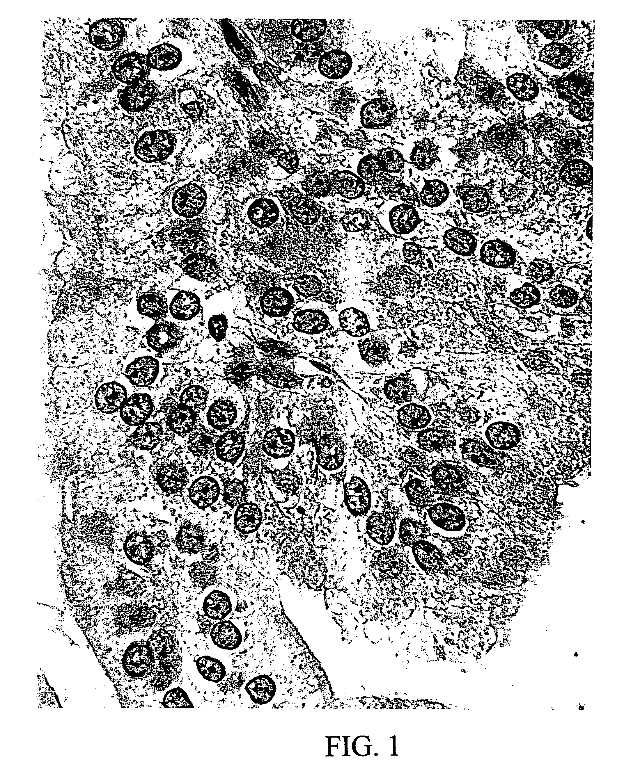
[0067]FIG. 25 shows a histopathologic section of urothelium taken from a region judged to be histologically normal at some distance from a papillary carcinoma lesion in a bladder. Nine nuclei in the image (identified by highlighted boundaries in the figure) were selected as suitable for analysis for their in-focus position. Upon digital analysis, two of these nuclei showed a nuclear signature resembling that of papillary carcinoma, even though visually the section was normal. Utilizing a computer graphic marker in the form of an outlining box, the diagnostic information is revealed directly on the image, thereby providing a visual, quantitative diagnostic clue not otherwise detectable from the image.

example 2

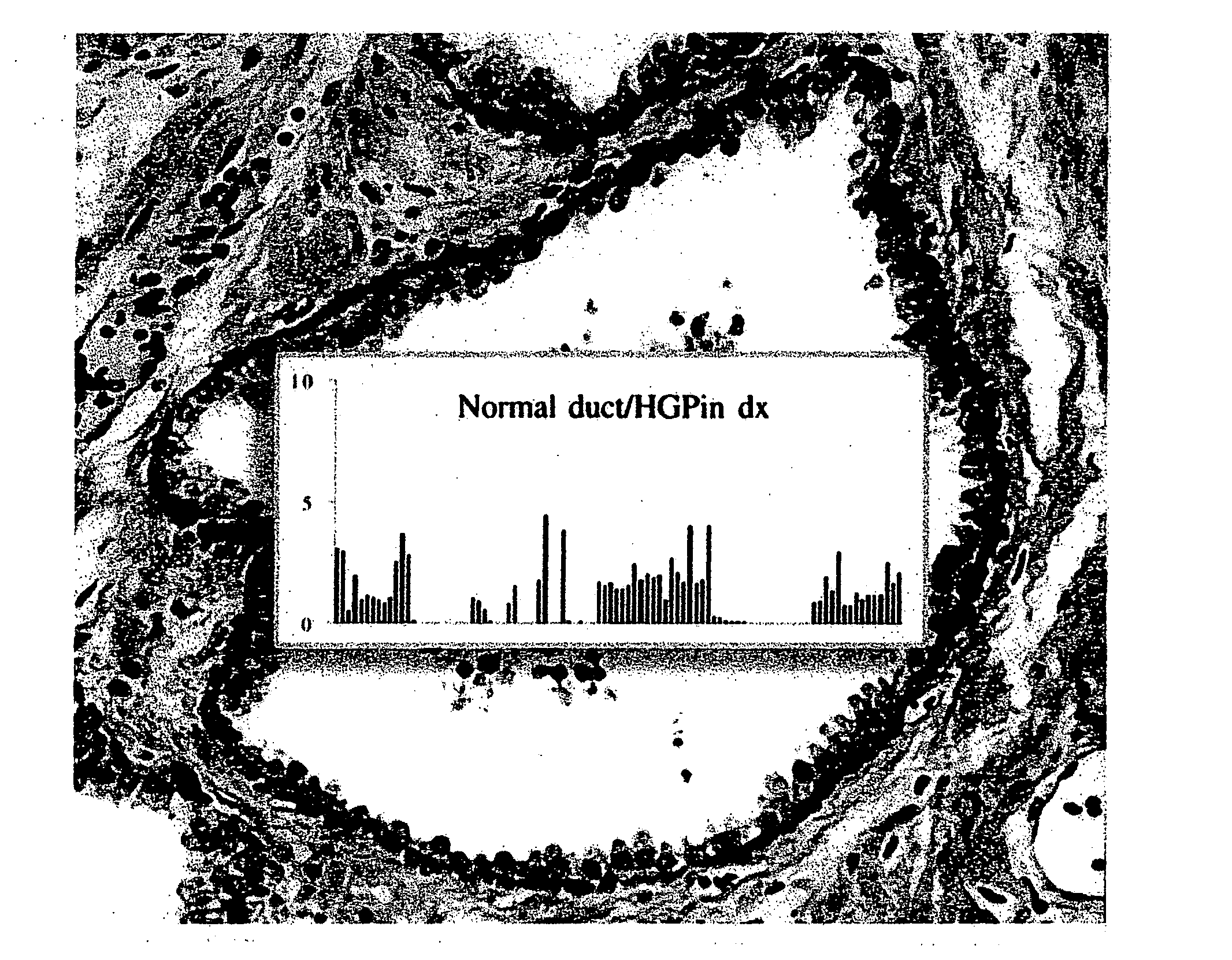
[0068] A tissue sample from a prostate gland duct was sectioned, fixed and stained with hematoxylin / eosin. The resulting slide was scanned with a high numerical aperture microscope objective to produce an image of the sample, as shown in FIG. 26. The image exhibits all criteria for a normal gland, such as a single-layered epithelium and a basal cell layer without gaps. However, a numeric analysis of the chromatin pattern of the nuclei revealed an overall signature known to be typical of a “normal appearing gland” in the vicinity of a prostatic intraepithelial neoplasia (PIN) lesion. FIG. 27 illustrates the signature of the imaged sample (seen in the middle of the figure) in comparison with the signatures of normal tissue (above) and cancerous tissue (below).

[0069] According to one approach, the signature profile of the epithelium is displayed superimposed on the image of the stained sample to reveal the diagnostic clue that is not otherwise visually perceptible, as illustrated in F...


PUM


Abstract

A microscope array with staggered rows of magnifying imaging systems is used to scan a biological tissue sample in a single linear pass to produce an image and corresponding optical-density data. A conventional computerized algorithm is used to identify, isolate and produce segmented images of nuclei contained in the image. The OD values corresponding to nuclear chromatin are used to identify numerical patterns known to have statistical significance in relation to the health condition of the biological tissue. These patterns are analyzed to detect pre-neoplastic changes in histologically normal-appearing tissue that suggest a risk for the development of a pre-malignant and a potentially malignant lesion. This information is then converted to a visually perceptible form incorporated into the image of the tissue sample and is displayed for qualitative analysis by a pathologist.

Description

RELATED APPLICATIONS [0001] This application is a continuation-in-part application of U.S. Ser. No. 10 / 637,486, filed Aug. 11, 2003, which is based on PCT / US02 / 08286, filed Mar. 19, 2002, and claims the benefit of priority of U.S. Provisional Application No. 60 / 276,498, filed Mar. 19, 2001, under 35 U.S.C. Sect. 119, and is also a continuation-in-part application of U.S. Ser. No. 10 / 602,756, filed Jun. 24, 2003.BACKGROUND OF THE INVENTION [0002] 1. Field of the Invention [0003] This invention is related in general to the field of light optical microscopy. In particular, it relates to a method and apparatus for conducting diagnostic testing of biological tissue with an array scanning microscope. [0004] 2. Description of the Related Art [0005] Changes in the cellular structure of tissue are used to detect pathologic changes, to assess the progress of precancerous conditions, and to detect cancer. A tissue sample removed from a patient is typically sectioned and fixed to a slide for st...

Claims


Application Information

Patent Timeline
IPC IPC(8): G06K9/00
CPCG02B21/002G06K9/00127G02B21/365G06V20/69
Inventor BARTELS, PETER H.
Owner DMETRIX INC
Why Eureka
Try Eureka