Compressor vibration damper

a compression pump and vibration damper technology, applied in the direction of positive displacement liquid engines, piston pumps, liquid fuel engines, etc., can solve problems such as performance degradation

Inactive Publication Date: 2007-08-02
LG ELECTRONICS INC
View PDF28 Cites 6 Cited by
  • Summary
  • Abstract
  • Description
  • Claims
  • Application Information

AI Technical Summary

Problems solved by technology

In these or other compressors, or indeed in other types of mechanical devices, internal vibrations are generated which tend to degrade performance.

Method used


Image

  • Compressor vibration damper
  • Compressor vibration damper
  • Compressor vibration damper

Examples


Embodiment Construction

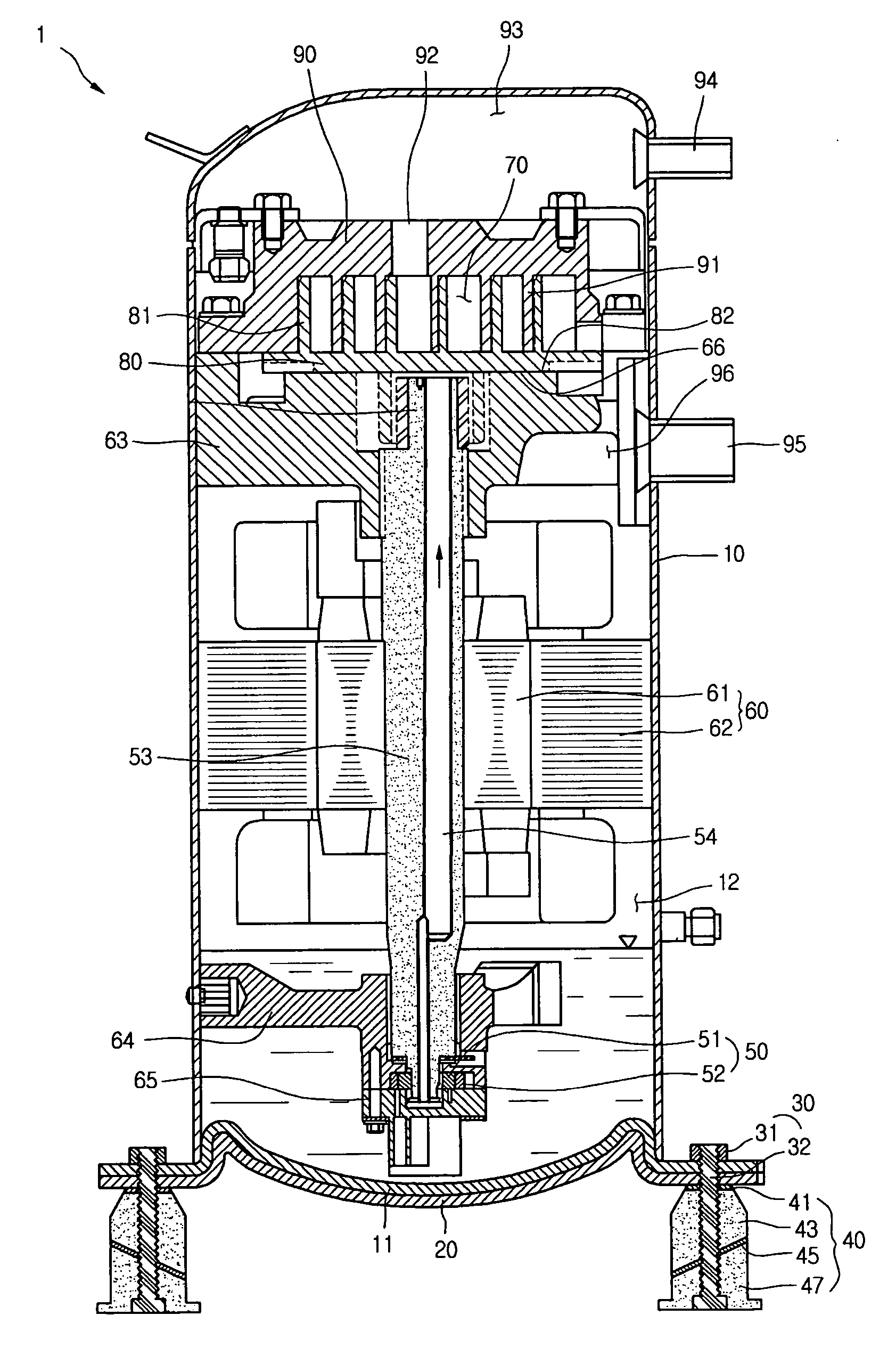
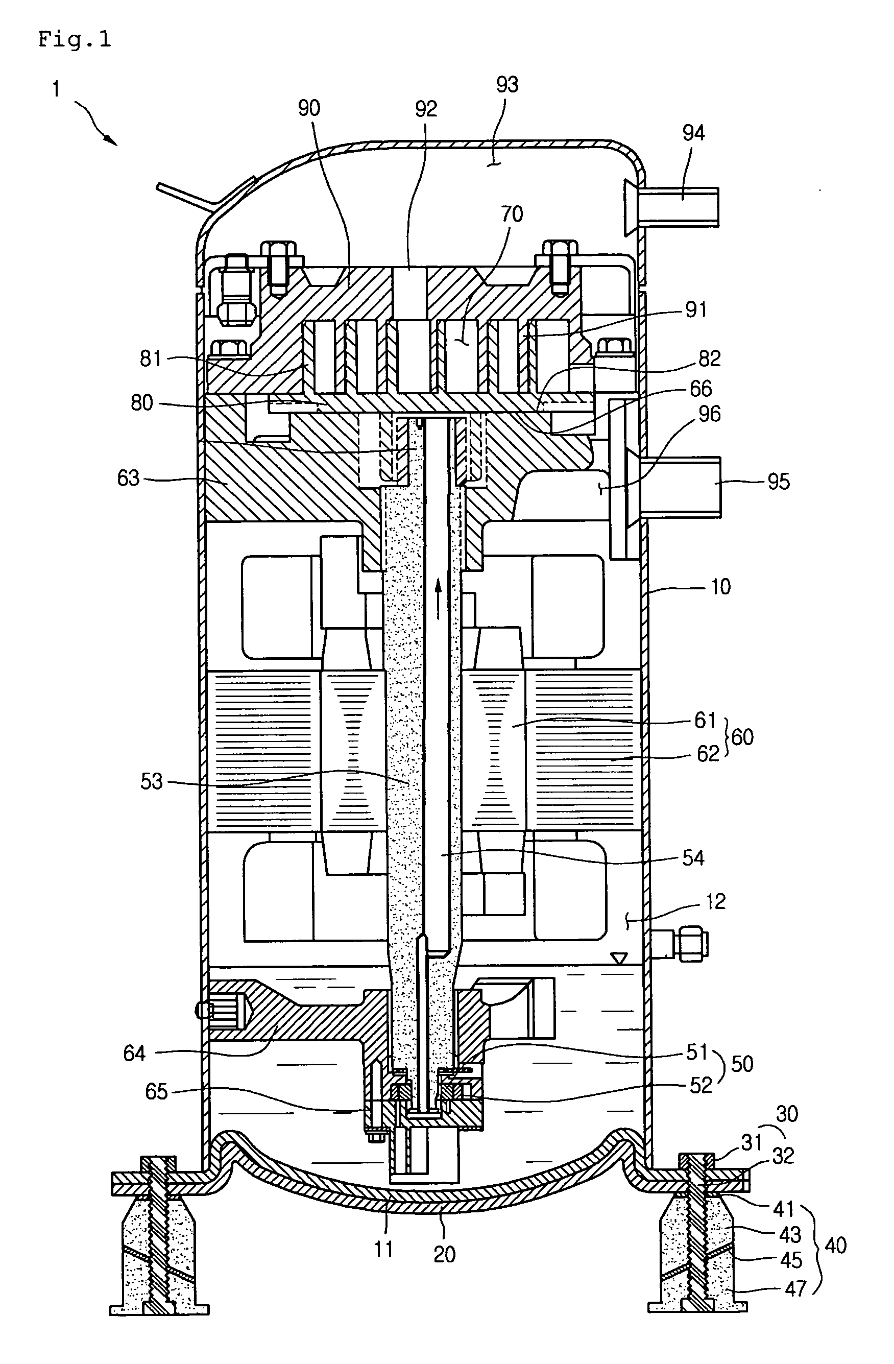
[0013] Scroll compressors may be categorized as high-pressure compressors or low-pressure compressors. In a low-pressure compressor, intake gas is filled in a casing, while in a high-pressure compressor discharge gas is filled in the casing.

[0014] One type of low-pressure scroll compressor includes a driving motor, a driving portion, an upper frame, and an intake conduit. The driving motor is formed from a rotor and a stator. The driving portion is rotated by the driving motor and includes a driving shaft having an oil-feeding passageway. The upper frame is inserted in an upper portion of the driving shaft and fluid enters through the intake conduit.

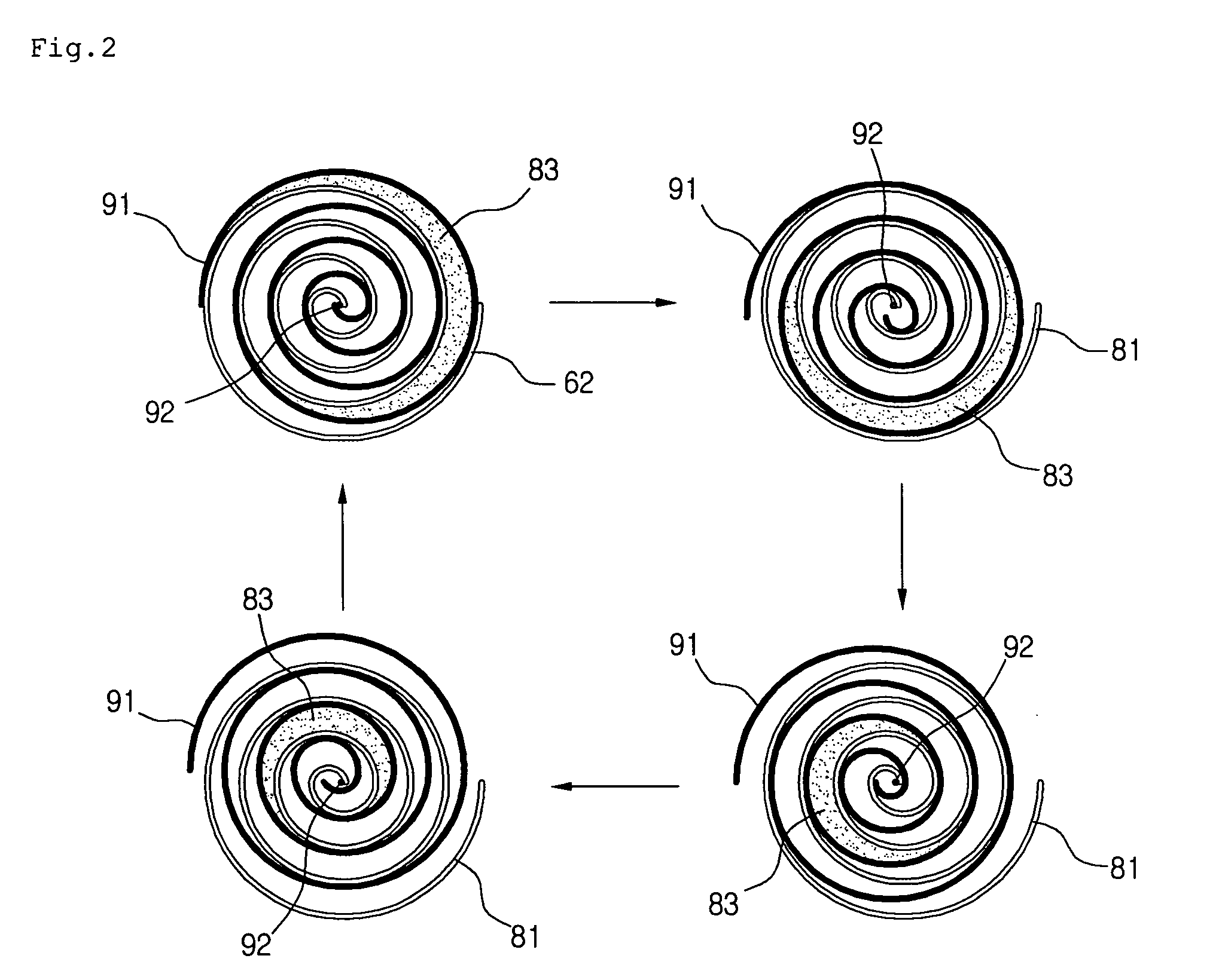
[0015] The scroll compressor may also include a scroll compression portion and a discharge conduit. The scroll compression portion includes an orbiting scroll and a fixed scroll. The orbiting scroll is formed on an upper portion of the upper frame and operates to compress a refrigerant drawn in through the intake conduit. The fixed scr...


PUM


Abstract

A vibration damper includes a first damping member coupled to a compressor, a second damping member coupled to the first damping member, and a dispersion member between the first and second damping members to disperse torsional vibration forces from the compressor. The dispersion member may also serve to disperse axial and torsional vibration forces received from the compressor through the first damping member.

Description

BACKGROUND [0001] 1. Field [0002] One or more embodiments described herein relate to dampening vibration in a mechanical device. [0003] 2. Background [0004] Compressors are used in various applications to compress gas or liquid. Examples of compressors include reciprocating compressors, scroll compressors, vane compressors, and centrifugal compressors. Scroll compressors are often used in refrigerators and air conditioners. In these or other compressors, or indeed in other types of mechanical devices, internal vibrations are generated which tend to degrade performance.BRIEF DESCRIPTION OF THE DRAWINGS [0005] The embodiments will be described in detail with reference to the following drawings in which like reference numerals refer to like elements wherein: [0006]FIG. 1 is a diagram showing a cross-sectional view of one embodiment of a scroll compressor that includes a vibration damper; [0007]FIG. 2 is a diagram showing a refrigerant compression process that may be performed in the sc...

Claims


Application Information

Patent Timeline
Patent Type & Authority Applications(United States)
IPC IPC(8): F04B35/00
CPCF04C18/0215F04C2270/12F04C23/008F04C18/02F04C29/00
Inventor SUH, JEONG HWANKIM, SEUNG YUPSHIN, DONG KOO
Owner LG ELECTRONICS INC
Why Eureka
Try Eureka