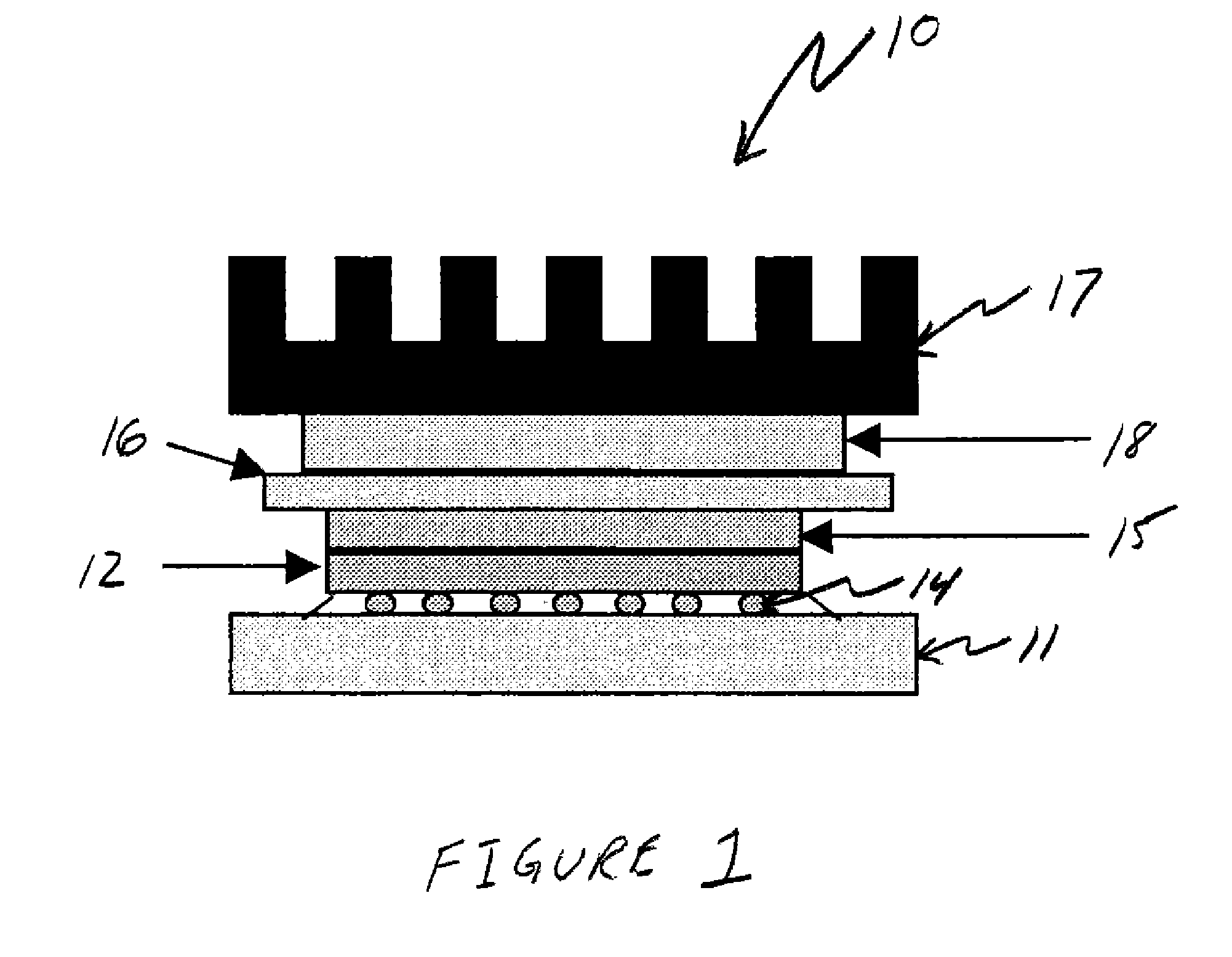
Thermal Interface Material

a technology of thermal interface material and material, which is applied in the direction of solid-state devices, tyre parts, vehicle components, etc., can solve the problems of difficult handling of paste or grease materials, drawbacks of thermally conductive materials such as greases, pastes and pads, and electrical devices such as those containing semiconductors, which typically generate a significant amount of heat during operation

Inactive Publication Date: 2007-08-02
HENKEL KGAA
View PDF8 Cites 35 Cited by
  • Summary
  • Abstract
  • Description
  • Claims
  • Application Information

AI Technical Summary

Benefits of technology

[0004] A composition for use as a thermal interface material in a heat-generating, semiconductor-containing device is provided. The composit

Problems solved by technology

Electronic devices, such as those containing semiconductors, typically generate a significant amount of heat during operation.
The current phase change materials, greases, pastes and pad thermally conductive materials have drawbacks that present obstacles during their use.
In addition to enhanced controls during application, the handling of the

Method used


Image

  • Thermal Interface Material

Examples


example 1

[0019] A thermal interface material (Formulation A) was formulated as shown Table 1 (all percents are in weight percent). The acrylic polymer, solid epoxy, and acrylate rubber were dissolved in methyl ethyl ketone. Next, the ingredients were added stepwise into a mixing vessel. The mix vessel was placed under an air driven mixer and the materials were mixed for 20 minutes. Next, the materials were de-gassed and coated at 5 ft / min onto a silicone treated carrier substrate. Following the coating of the material, the film is dried at 75° C. for 20 minutes to remove solvent.

TABLE 1Thermal Interface Formulation AMaterialWeight PercentAcrylic Polymer112Acrylate212Liquid DGBEA310.4Solid Epoxy43.6Surface Agent51Surface Agent61Conductive Filler760

1SG80H-DR

2AR-14

3ARALDITE GY6010, commercially available from Vantico

4EPON 1001f, commercially available from Resolution

5FLUOROLINK F10, commercially available from Solvay Solexis

6FLUOROLINK S10, commercially available from Solvay Solexis

7bor...


PUM

PropertyMeasurementUnit
Temperatureaaaaaaaaaa
Percent by massaaaaaaaaaa

Abstract

A composition for use as a thermal interface material in a heat-generating electronic device is provided. The composition comprises a blend of acrylic polymer, one or more liquid resins, conductive filler particles and optionally one or more solid resins.

Description

FIELD OF THE INVENTION [0001] This invention relates to a thermally conductive material that is utilized to transfer heat from a heat-generating electronic device to a cold sink that absorbs and dissipates the transferred heat. BACKGROUND OF THE INVENTION [0002] Electronic devices, such as those containing semiconductors, typically generate a significant amount of heat during operation. In order to cool the semiconductors, cold sinks are typically affixed in some manner to the device. In operation, heat generated during use is transferred from the semiconductor to the cold sink where the heat is harmlessly dissipated. In order to maximize the heat transfer from the semiconductor to the cold sink, a thermally conductive thermal interface material is utilized. The thermal interface material ideally provides an intimate contact between the cold sink and the semiconductor to facilitate the heat transfer. Commonly, either a paste-like thermally conductive material, such as silicone greas...

Claims


Application Information

Patent Timeline
IPC IPC(8): C08K3/22
CPCC08C19/06H01L2224/73204C08L15/00C08L33/02C08L33/08C08L63/00C09J9/02C09J11/04H01L23/3737H01L2224/16H01L2224/73253H01L2924/01078H01L2924/01079C08L13/00H01L2224/32245H01L2224/32225H01L2224/16227H01L2224/16225H01L2924/10253H01L2924/01019C08L2666/04H01L2924/00C08K3/10C08K3/00
Inventor COLLINS, ANDREWCHENG, CHIH-MIN
Owner HENKEL KGAA
Why Eureka
Try Eureka