Ophthalmic sulcus speculum

a sulcus speculum and ophthalmology technology, applied in the field of ophthalmology devices, can solve the problems of limiting the distance that the lid can be retracted, limiting the working area and visibility, and “squaring” the view

Inactive Publication Date: 2007-08-02
FOULKES RICHARD B
View PDF48 Cites 8 Cited by
  • Summary
  • Abstract
  • Description
  • Claims
  • Application Information

AI Technical Summary

Problems solved by technology

Problems with conventional speculums occur when the lid length is short, limiting the distance that the lids can be retracted, or when the eye is deep-set.
These two problems lead to a “squaring” of the view and limit the working area and visibility.
Additionally the lids tend to rise up when stretched tight, creating a potential space for fluid to pool.
Pooling of fluid limits visibility of the surgeon further and allows for bacteria and eye secretions to potentially enter the eye, especially in cataract surgery where a large amount of water is used in the extraction of the lens.
Elderly eyes become recessed from the loosening of the fat pads, which further complicates the view with water filling into the space formed by the recession.
Such a suction tube is rarely used in ophthalmic procedures as it represents an additional source of obstruction to view and free movement.
This passive method is reasonably effective in removing small amounts of fluid but fails in deep-set eyes and the wick often floats out of the eye.
Positioning the patient's head to be angled to the side can be helpful but often limits the microscopic view into the eye from obstruction by the nose or brow.
Some lid speculums for opening eyelids have hollow tubing with openings or holes formed therein, the tubing being attached to suction for removal of water or fluids from the orbital / ocular area These lid speculums can perform aspiration, however, the aspiration is often ineffective because the holes in these speculums are adjacent the lid margin which is often well above the corneal surface, making the holes incapable of removing the water.
The poor visibility encountered by the surgeon while operating on a patient increases the risk of a poor surgical outcome.
The risk of infection from this water getting into the eye is also increased.
In a small eye, the problem of fluid clearance is made worse by the tendency of the inner part of the cornea (stroma) to absorb water when the stroma is exposed.
The water slows the absorption of the 193 nm laser and alters the treatment shape leading to problems with the patient's vision correction including aberrational vision Currently, wicking methods and aspirating speculums are used but are often inadequate due to the raising of the ports of conventional aspirating speculums above the ocular surface.
Wicking dams can be helpful but are often overwhelmed by the tear film.
Manual removal of fluid by employing a sponge necessitates stopping the surgical procedure, which changes the hydration and dehydration of the cornea and reduces the precise standardization required to attain good surgical results for the patient.
These drugs are somewhat toxic to the anterior corneal surface and especially in refractive surgery many surgeons try to avoid drug exposure to the front surface by using a soaked sponge.
The result of slowing down or stopping is a wave on the surface to be lasered that can cause irregular vision If the obstruction is hard enough, the ring can be dislodged and a partial flap is created usually leading to an aborted procedure.
The most common cause of an obstruction is the microkeratome bumping into a lid speculum, especially in a tight eye.
Conventional fluid removal systems do not adequately reach the sulcus because such systems are attached to the lid margin and tend to rise away from the sulcus when lids are spread open, especially when such systems are attached to a small lid.

Method used


Image

  • Ophthalmic sulcus speculum
  • Ophthalmic sulcus speculum
  • Ophthalmic sulcus speculum

Examples


Embodiment Construction

)

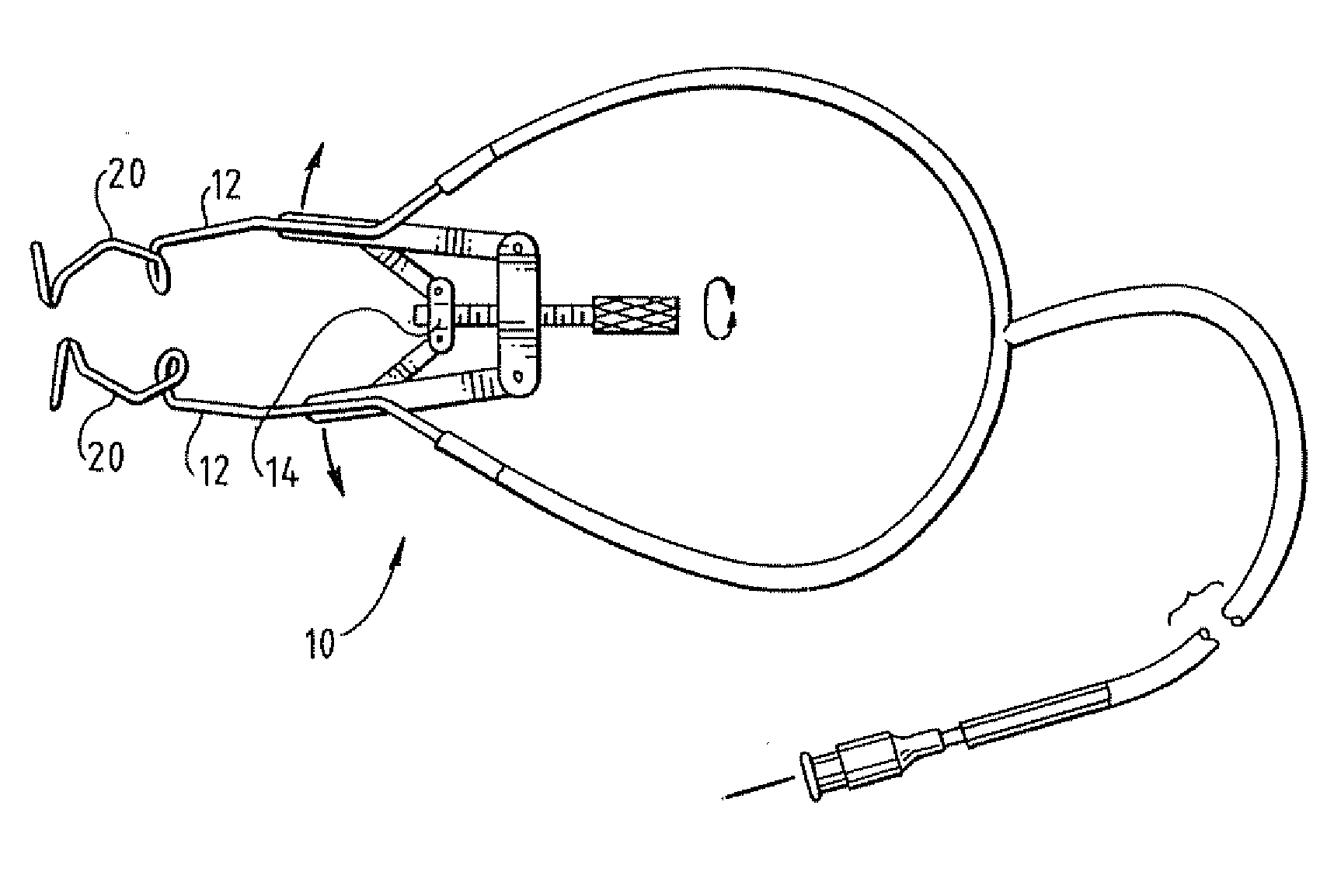
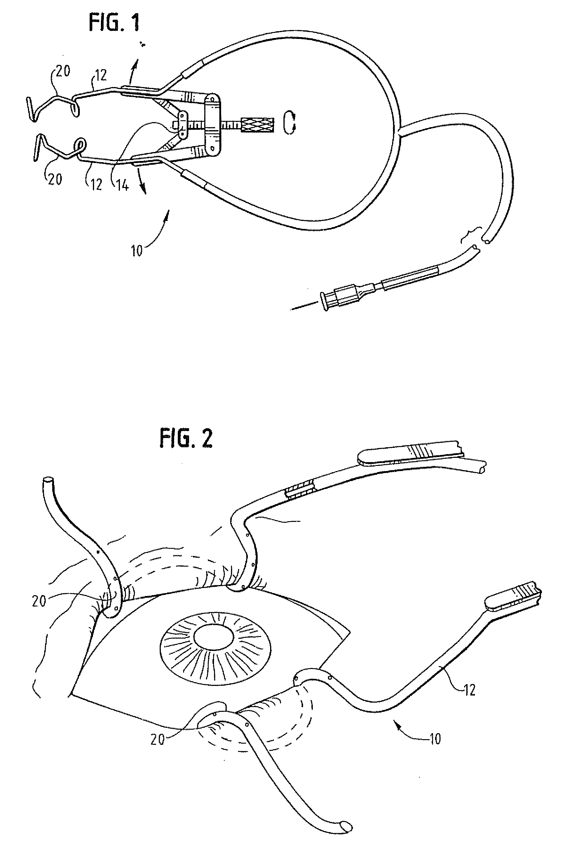
[0028]FIGS. 1 and 2 depict a conventional wire speculum 10, which is used to access the eye during ophthalmic procedures by spreading the lids The speculums depicted in FIGS. 1 and 2 employ a wire or blade to wrap around the eyelid margin several millimeters near the midpoint to spread the eyelids, thereby exposing the ocular surface.

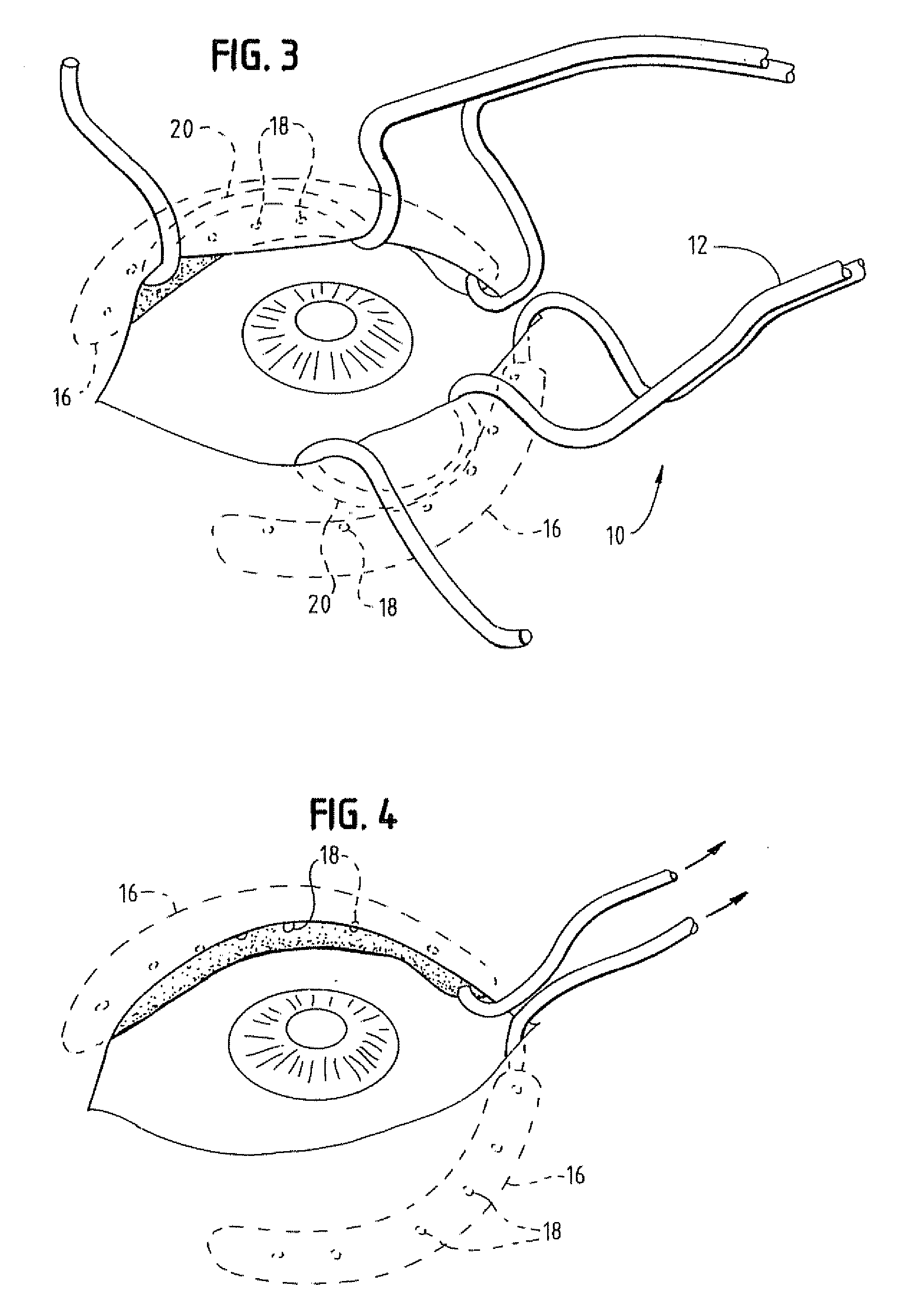
[0029] An embodiment of the present sulcus speculum is shown in FIG. 3 and includes a speculum 10. The speculum 10 includes a pair of arms 12 and can include a mechanism 14 for spreading the arms apart. At least one of the pair of arms 12 has a portion with a shape adapted for reaching under the eyelid of a patient to the sulcus. The arm portion with that shape will be referred to as the sulcus arm portion 16. In some embodiments the sulcus arm portion 16 can help hold the eyelid open during ophthalmic procedures.

[0030] As shown in FIG. 3, the sulcus arm portion 16 can have a hole or holes 18 for receiving fluid from the sulcus or for delivering drug...


PUM


Abstract

Devices in accordance with certain embodiments of the present sulcus speculum are designed to be placed into the sulcus of an eye to perform one or more of the following functions: evacuation of fluid, opening of the lids, and application of drugs such as anesthetic or antibiotics. The present devices can include a sponge positioned around (a) an aspiration tube for withdrawing fluid and (b) an arm of a speculum. Other variations of the present devices include those with an aspiration tube for withdrawing fluid, the tube being positioned in a trough defined by an arm of a speculum. Alternatively, the speculum arm can define a passage for holding the aspiration tube. In that alternate embodiment, the portion of the speculum arm defining the passage has openings for passing fluid into the passage so that the aspiration tube in the passage can then remove fluid.

Description

CROSS-REFERENCE TO RELATED APPLICATION (S) [0001] This application is related to and claims priority benefits from U.S. Provisional Patent Application Ser. No. 60 / 351,219 filed Jan. 22, 2002. The '219 provisional application is hereby incorporated by reference herein in its entirety.FIELD OF THE INVENTION [0002] Aspects of the present invention are directed to the field of ophthalmic devices. More particularly, aspects of the present invention are directed to speculums for placement adjacent the sulcus, which is the region under the eyelid where the covering of the lid and globe fold back on themselves, during ophthalmic procedures. BACKGROUND OF THE INVENTION [0003] A class of instruments known as speculums facilitates access to the eye during ophthalmic procedures by spreading the lids. Speculums are of many designs but lid speculums work by using a wire or blade to wrap around the eyelid margin several millimeters near the midpoint to spread the eyelids gaining exposure of the oc...

Claims


Application Information

Patent Timeline
Patent Type & Authority Applications(United States)
IPC IPC(8): A61B1/32A61B17/02A61F9/00A61M1/00
CPCA61B1/00094A61B1/32A61M2210/0612A61F9/0017A61M1/0084A61B17/0231A61M1/85
Inventor FOULKES, RICHARD B.
Owner FOULKES RICHARD B
Why Eureka
Try Eureka