

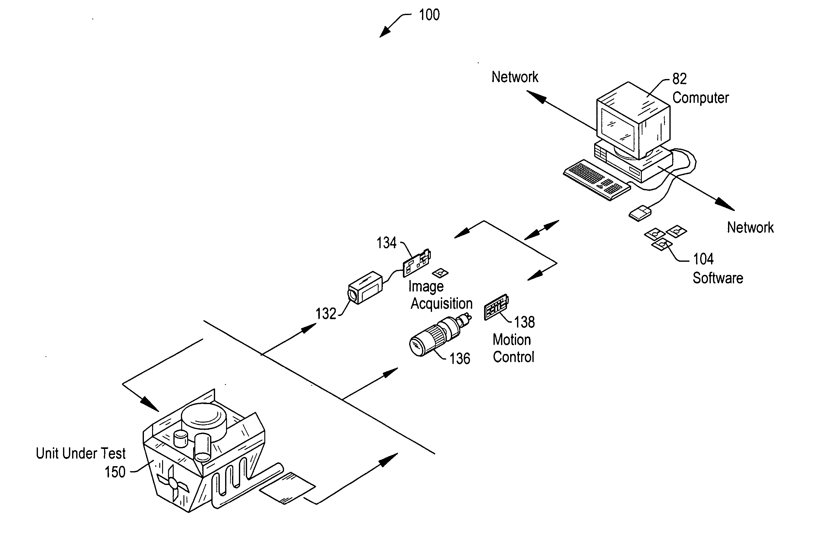
Automatically generating code from drawing specifications for use in motion control
a technology of motion control and drawing specifications, applied in the field of motion control, can solve the problems of overly complex, error-prone, tedious and difficult to understand, etc., and achieve the effect of easy understanding
- Summary
- Abstract
- Description
- Claims
- Application Information
AI Technical Summary
Benefits of technology
Problems solved by technology
Method used
Image

Examples
Embodiment Construction
Incorporation by Reference
[0033] The following references are hereby incorporated by reference in their entirety as though fully and completely set forth herein:
[0034] U.S. Pat. No. 4,914,568 titled “Graphical System for Modeling a Process and Associated Method,” issued on Apr. 3, 1990.
[0035] U.S. Pat. No. 5,481,741 titled “Method and Apparatus for Providing Attribute Nodes in a Graphical Data Flow Environment”.
[0036] U.S. Pat. No. 6,173,438 titled “Embedded Graphical Programming System” filed Aug. 18, 1997.
[0037] U.S. Pat. No. 6,219,628 titled “System and Method for Configuring an Instrument to Perform Measurement Functions Utilizing Conversion of Graphical Programs into Hardware Implementations,” filed Aug. 18, 1997.
[0038] U.S. patent application Ser. No. 10 / 051,474 titled “System and Method for Graphically Creating a Sequence of Motion Control Operations,” filed Jan. 18, 2002.
[0039] U.S. patent application Ser. No. 10 / 051,268 titled “System and Method for Programmatically...
PUM
 Abstract
Description
Claims
Application Information