Surveying instrument with compensation for mechanical errors

a technology of mechanical errors and surveying instruments, applied in surveying instruments, instruments, height/levelling measurement, etc., can solve the problems of reducing accuracy and easy mechanical shock of the surveying means, and achieve the effect of improving the accuracy of the aiming of the instrument, reducing the need for user interaction, and reducing the mechanical inaccuracy of the surveying instrumen

Active Publication Date: 2007-08-09
TRIMBLE INC
View PDF7 Cites 28 Cited by
  • Summary
  • Abstract
  • Description
  • Claims
  • Application Information

AI Technical Summary

Benefits of technology

[0024] This solution allows for larger mechanical inaccuracy in the surveying instrument while achieving improved accuracy in the aiming of the instrument. Moreover, this solution enables an operator to aim in a desired direction with less required user interaction. For example, when an operator wishes to move the aim of the sight line from a first target in a first horizontal direction and a first vertical direction to a second target in the same horizontal direction but at a different second vertical direction; Then this method enables the operator to achieve that goal by the simple action of operating a vertical control knob only so as to change the vertical reference value. Whereas a prior art instrument, when being operated with the vertical control knob only, causes a slight shift in the horizontal aim due to inherent mechanical inaccuracies in the instrument and to leveling errors, the instrument according to an embodiment of the invention compensates for such inaccuracies.
[0025] Additionally this solution advantageously also allows for lower production costs of the surveying instrument, since the need for mechanical trimming of the instrument in connection with its production may be eliminated, or at least reduced.
[0026] Moreover, this solution enables manufacture of a more sturdy and stable surveying instrument, since some mechanical trimming means can be eliminated. Such mechanical trimming means are often vulnerable to mechanical shock, which may render a reduced accuracy when using a surveying instrument with such mechanical trimming means after having exposed it to mechanical shock e.g. by bringing it on a bumpy ride in a car.
[0027] Rather than mechanically trimming the surveying instrument to adjust e.g. the mutual position of the first axis and second axis in connection with manufacture, the aim of the surveying instrument according to an aspect of the invention is automatically adjusted so as to compensate for any mechanical errors. The elimination of mechanical trimming means reduces the mechanical complexity of the instrument and it eliminates or reduces the need for mechanical trimming during the production of the surveying instrument. Therefore this solution allows for lower production costs. This is because the error determination mechanism is not subject to the mechanically induced errors inherent in the fundamental design of the instrument, but is totally independent. By determining the exact error as a function of the two different axes of rotation, relative to an independent reference system, and automatically incorporating the corrections needed to exactly compensate for the mechanical errors, the invention produces an improved level of accuracy in the actual measurements, and true orthogonality of axis movement; this in turn produces much greater conformity to true vertical and horizontal repositioning by the user.
[0028] This solution makes it possible to accurately indicate a vertical line on a wall using the apparatus according to an aspect of the invention, even when the apparatus is mounted in a non-ideal position, e.g. if the apparatus is not exactly leveled.
[0029] This solution makes it possible to accurately indicate a horizontal line or a line between two points on a wall using the apparatus according to an aspect of the invention, even when the apparatus is mounted in a non-ideal position, e.g. if the apparatus is not exactly leveled. The expression “on a wall” may of course not necessarily indicate that the line is on a wall but rather that the line is straight and essentially perpendicular to the measuring / indicating beam.

Problems solved by technology

However, using still another error in the compensation will give a better result and using all three of the errors will of course improve the result.
Such mechanical trimming means are often vulnerable to mechanical shock, which may render a reduced accuracy when using a surveying instrument with such mechanical trimming means after having exposed it to mechanical shock e.g. by bringing it on a bumpy ride in a car.

Method used


Image

  • Surveying instrument with compensation for mechanical errors
  • Surveying instrument with compensation for mechanical errors
  • Surveying instrument with compensation for mechanical errors

Examples


first embodiment

a Control System

[0060]FIG. 3 shows a schematic block diagram of a first embodiment of a control system 200 for use in a surveying instrument 10 of the type shown in FIG. 1.

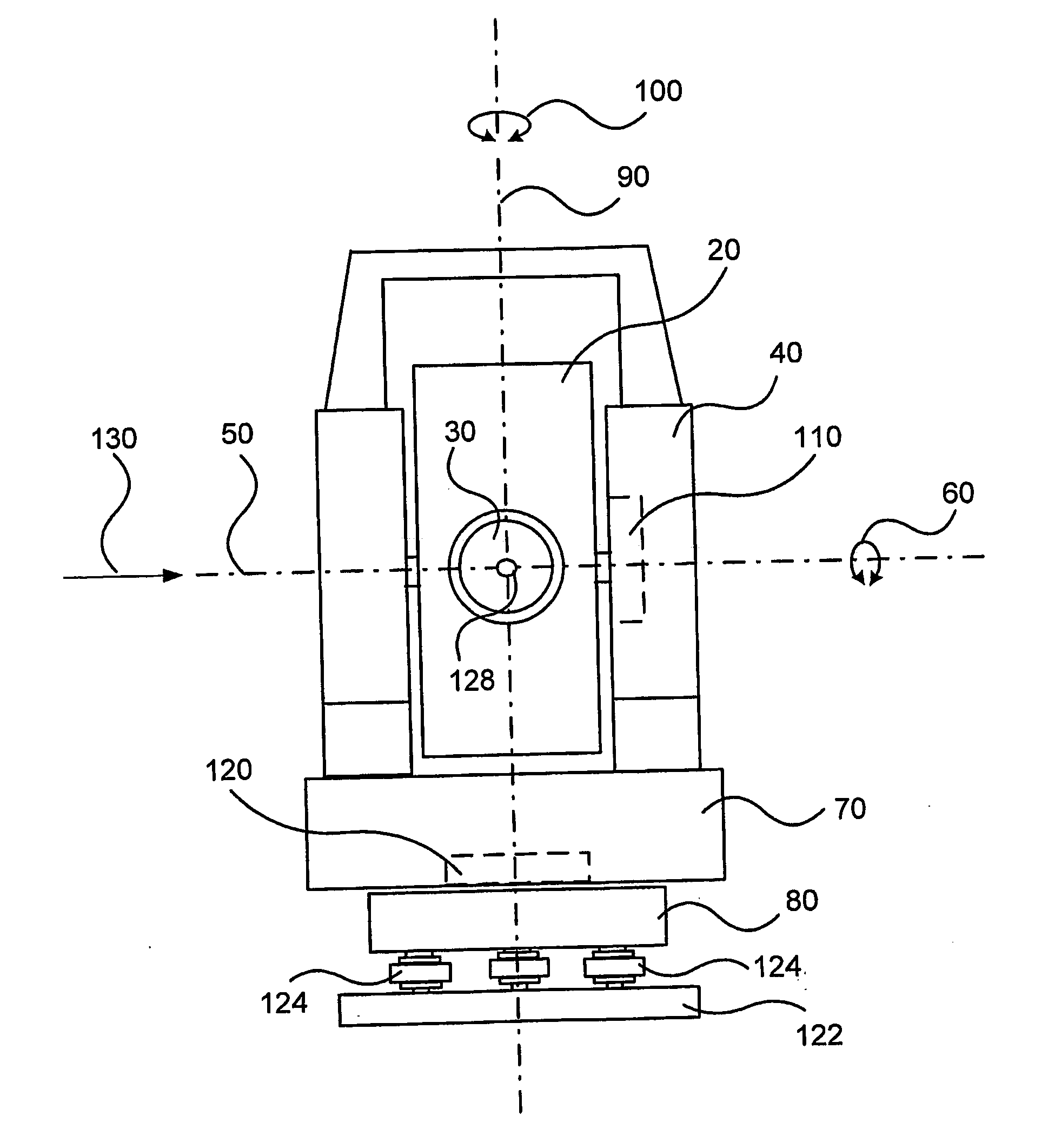
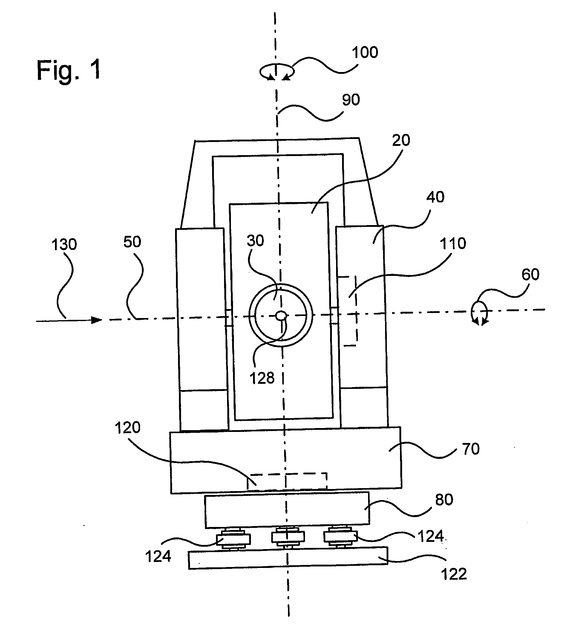
[0061] As indicated above, driver 110 is adapted to cause the movement of the movable unit 20 around the first axis 50, also referred to as the trunnion axis. The angle of deviation of the sight line from a truly vertical line is herein denoted V. Hence, activation of driver 110 is the main cause for change of the angle V.

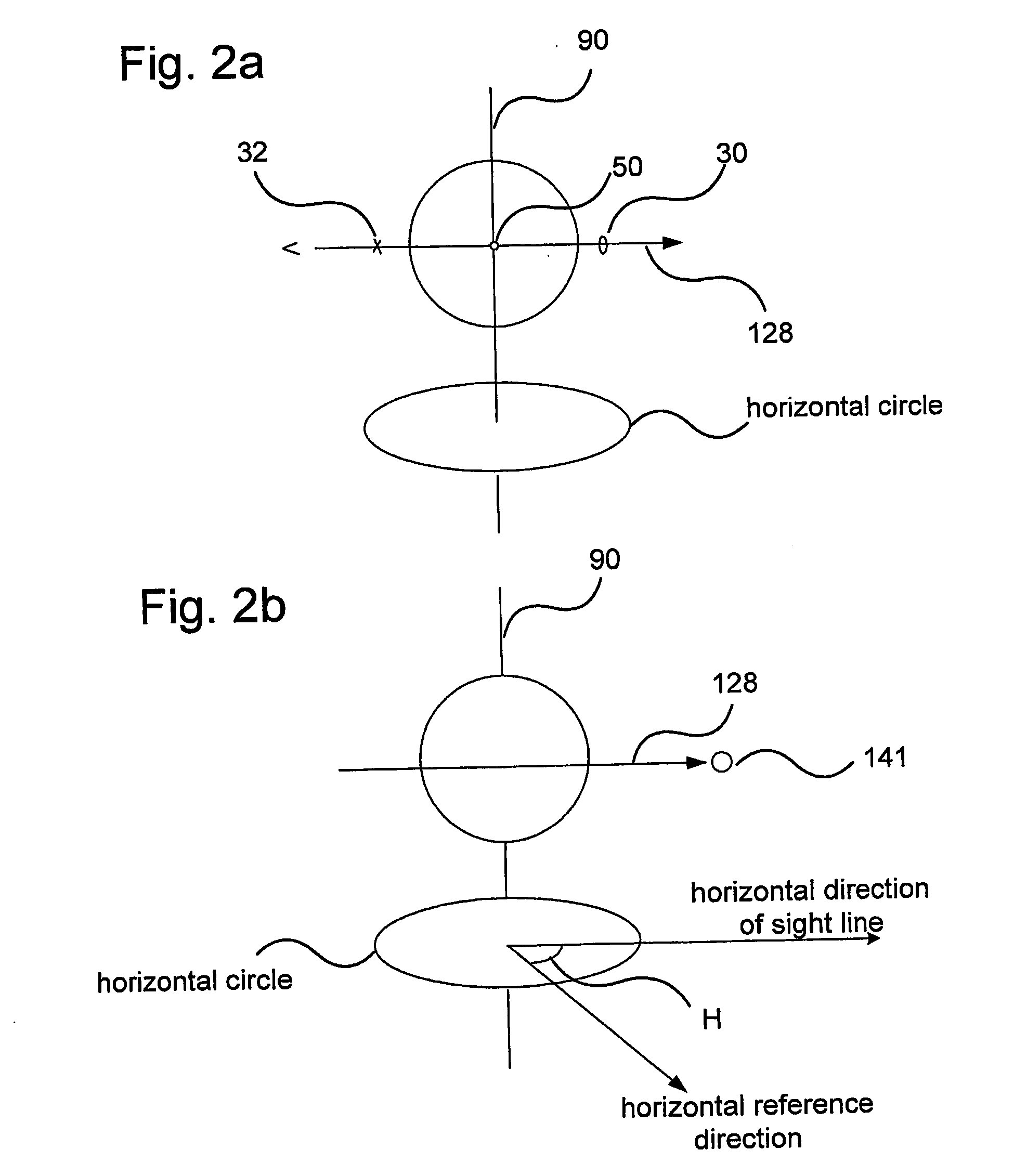
[0062] Likewise, driver 120 causes the movement of the housing 40 around the second axis 90. The angle H is the angular deviation from a horizontal reference direction. The reference direction may, e.g. be the direction towards north. Hence, activation of driver 120 is the main cause for change of the angle H.

Control of Vertical Output Value V

[0063] With reference to FIG. 3, a sensor 210 is provided for detecting the vertically angular position of the movable unit 20 relative to the alidade ...

second embodiment

a Control System

[0119]FIG. 5 shows a schematic block diagram of a second embodiment 200B of a control system for use in a surveying instrument 10 of the type shown in FIG. 1. The control system 200B operates to control the drive arrangements 110 and 120, respectively.

Vertical Aim

[0120] The control system 200B according to the second embodiment includes a vertical sensor 210 delivering a detected signal Vs to an input 271 of a vertical position generator 272. The vertical position generator 272 also has an input 273 for receiving a vertical error correction value VEC. The vertical position generator 272 generates an accurate vertical position value V in response to the values received on the inputs 271 and 273.

[0121] The output signal V is delivered to an input 274 of a first controller 280. The first controller 280 also comprises an input 290 for a reference signal value Rv which may be set by a user or operator. The reference signal value Rv is indicative of a desired value for...


PUM


Abstract

The invention relates to a method of operating a surveying instrument (10) placed in a orthogonal XYZ-system at (0,0,0) having a movable unit (20), said instrument defining a sight line (128) that is controllably rotatable around a first axis (50), essentially horizontal, and around a second axis (90), essentially vertical, wherein said second axis (90) may be inaccurately positioned so that it deviates from a true vertical axis, and said first axis (50) may deviate from being orthogonal to the second axis (90); the method comprising the steps of determining at least one of the following group of errors relating to the instrument and/or its location: a) a trunnion axis error T as a function of the deviation from 90 degrees between the first axis (50) and the second axis; b) a horizontal collimation error CH, being the deviation between the sight line (128) and the perpendicular angle as related to the first axis (50); and c) a total plumb error defined by components, PI and PII, being two separate angular values defining the tilt of the instrument as related to the plumb line through the same; and d) using these determined values in continuously controlling the alignment when aiming the instrument. The invention also relates to a surveying instrument for use with the method and an error compensation system for a surveying instrument.

Description

TECHNICAL FIELD OF THE INVENTION [0001] The present invention relates to a surveying instrument, and to a method of operating a surveying instrument. FOR THE PURPOSE OF THIS DESCRIPTION AND CLAIMS [0002] The following wordings should for the purpose of this description and claims be understood to define the listed descriptions: [0003] (0,0,0) in a right handed X,Y,Z-coordinate system to be a point on the sightline of the surveying instrument and in the middle of the same for the purpose of the calculations. This coordinate system may of course be transformed into any other system having its (0,0,0) placed elsewhere. [0004] Horizontal angle H is defined by the angle between the Y-axis and the projection in the XY-plane of a line through the origin of the coordinate system and an arbitrary point P. [0005] Vertical angle V is defined as the angle between the Z-axis and the sightline to the arbitrary point aimed at. [0006] Aiming should in this context be taken not only as aiming at a s...

Claims


Application Information

Patent Timeline
Patent Type & Authority Applications(United States)
IPC IPC(8): G01C5/00G01CG01C5/02G01C15/00
CPCG01C15/002G01C25/00G01C15/004
Inventor HERTZMAN, MIKAEL
Owner TRIMBLE INC
Why Eureka
Try Eureka